
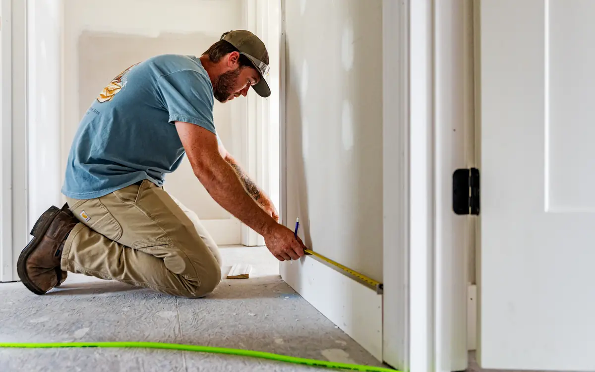
A level run that closed at 1.204 metres
Twelve metres of north wall on a detached annexe, eight metres of gable at each end, and the staff read 1.204 m of difference between the two ends of the long wall before the run closed back on the datum peg within four millimetres. The trial pit found firm clay at 750 mm and the engineer has called trench fill founded at 900, with the top of the pour stopped a couple of courses down so the blockwork can start on it. On paper that is one line of footing 40 m long, 600 wide, 750 of concrete in it, and it prices in about ninety seconds.
It is not one footing. It is a dozen or more separate level pours that have to hand load to each other across a lap, and every one of those handovers is a decision somebody makes — either at the setting-out stage with a tape and a course rod, or at half past seven on the morning of the pour with a truck turning in the road. The four things to settle are how many steps there are, how tall each one is allowed to be, how far the upper pour has to run past the lower one, and whether the whole run goes in on one ticket behind stop-end boards or comes in over two days across joints you have to make deliberately.
None of that is difficult. What is difficult is that the answers move each other. A taller step means fewer of them and fewer boards, and on deep trench fill it costs no extra lap, which is not what most people expect. A shorter step keeps the concrete closer to the ground surface and hands the difference straight to the bricklayer as courses below the damp course. And whichever you pick, the quantity is not the forty by six-tenths by three-quarters somebody wrote on the back of the drawing.
Two falls, and only one of them is drawn
The gradient on the topographical survey is the site's, measured down the line of maximum fall, and it is almost never the gradient you build to. What the footing sees is the fall along its own line, and a wall set at an angle to the line of maximum fall sees the site gradient multiplied by the cosine of that angle. It is worth having the number rather than the intuition: at thirty degrees off the line of maximum fall a wall has lost only thirteen per cent of the gradient, but at sixty degrees it has lost half of it, and at ninety it is dead level and takes no steps at all. On a rectangle set square to the contours, two walls do all the stepping and the other two are level runs at different heights.
So level along the wall lines and do it after the setting out, because the building rarely lands where the survey assumed. Take a reading at every profile and every intended step position, work off one bench mark that will survive to the slab, and close the run back onto it. A traverse that closes badly over a 40 m perimeter is telling you something about the staff, the tripod or the ground, and finding out now costs a quarter of an hour.
Then take the second fall, the one nobody levels: the fall of the bearing stratum. Ground surface and founding stratum are two surfaces under no obligation to be parallel. A hillside with a clay head over rock frequently has a formation dipping steeper than the topsoil, and a made-up garden on a fall can have one running the other way entirely under a metre of imported fill. The steps follow the worse of the two, because the depth rule has to hold everywhere along the run rather than on average. Two trial pits, one at each end of the falling wall, settle it — and where they disagree with the ground surface by more than a step, the stratum is setting the step positions and the survey is not.
| Angle between the wall and the line of maximum fall | Gradient along that wall | Fall over 12 m | Whole 225 mm steps in it, and what is left over |
|---|---|---|---|
| 0 degrees — straight down the slope | 10.00% (1 in 10) | 1.200 m | 5, and 75 mm |
| 15 degrees | 9.66% (1 in 10.4) | 1.159 m | 5, and 34 mm |
| 30 degrees | 8.66% (1 in 11.5) | 1.039 m | 4, and 139 mm |
| 45 degrees | 7.07% (1 in 14.1) | 0.849 m | 3, and 174 mm |
| 60 degrees | 5.00% (1 in 20) | 0.600 m | 2, and 150 mm |
| 90 degrees — along the contour | 0% | 0 m | none; the run is level |
Feed it the rise and run you actually levelled along one wall line — 1.204 m over 12.000 m, not the survey's headline gradient — and read the percentage. Run it a second time for the formation levels out of the two trial pits. If the two answers differ by more than about a step height, the trial pits are setting your step positions and the ground surface is not.
The vertical change in height over the run.
The horizontal distance over which the rise occurs.
Slope grade
8.974 %
- Angle
- 5.13 degrees
They open the calculator with your figures already in it
Slope & Grade Calculator: 8.97 % — shown in imperial, US market. The link sets both, so the result they see is the one on your screen.
What this calculation does not cover
- Run is taken as the true horizontal distance between the two ends, and nothing converts a tape laid along the sloping face into that horizontal — measure along the surface instead and the grade reads lower than the ground really is, with the gap widening as the slope steepens.
- Rise is read as a magnitude only, so a drop and a climb of the same size return the same positive grade and a negative entry is floored to zero; which end is higher stays your own note rather than something the answer carries.
- Both figures describe a single straight line drawn between the two points you measured, so any crest, dip or bench sitting between them is averaged away, and cross-fall across the width of a drive or path is not part of the arithmetic at all.
- The output covers grade percent and the matching angle; the sloping distance itself — what you would order ramp board, handrail or edging against, and always longer than the run — is not worked out, nor is the result expressed as the 1-in-X ratio that specifications are often written in.
- No ceiling is applied to the outcome: a 2% fall and a 45% bank come back with identical confidence, and the accessible-ramp and driveway grade figures quoted in the questions below are context for reading your number, not a test the calculation runs against it.
A step is a lap, and trench fill is lapped by its own rule
A step is a splice in a load path. The wall above runs continuously through it, but the concrete under that wall stops at one level and restarts lower down, so for a short distance the load has to travel through a region where the upper pour is bearing on the lower pour rather than on the ground. That is what the lap is: the length over which the two pours share, and it is dimensioned so the load spreads out of the upper section and into the lower one before the upper section runs out.
In England and Wales the arithmetic is published, and it is published twice — which is the part that gets missed. Approved Document A, Section 2E, caps the step the same way for everything: no step may be taller than the thickness of the foundation. Then it splits. A strip foundation is lapped by the greatest of twice the height of the step, the thickness of the foundation, or 300 mm. Trench fill is not: for trench fill the lap is the greater of twice the height of the step or one metre, and the thickness of the concrete does not enter it at all. Read the current edition rather than a memory of one, because the plain-concrete section is one of the parts that has been re-set between editions and the diagram numbers have moved with it.
Carrying the strip formula onto trench fill is the common error, and it goes wrong in both directions. On a conventional 225 mm strip the step is capped at 225 mm and twice the step is 450 mm, so the step drives the lap and the thickness never gets a look in. On 750 mm trench fill the strip formula would say 750 mm and the actual answer is a metre, so the run is short by 250 mm at every step. On 1.20 m trench fill the strip formula would say 1.20 m and the actual answer is still a metre, so the same habit now over-orders. The rule that matters on trench fill is the flat metre: a 225 mm step, a 300 mm step and a 450 mm step all lap one metre, and below a 500 mm step making the step shorter buys nothing at all. That runs against the instinct on almost every sloping-site job — on trench fill the cheap direction is a taller step and fewer of them, not a gentle staircase, and no amount of extra depth lengthens the lap.
The American codes handle the same problem with a different emphasis, and it is fairer to say so than to import the British formula and pretend. The International Residential Code, at Section R403.1.5, requires the top surface of a footing to be level, allows the soffit a slope of no more than one in ten, and requires stepping wherever the top has to change level or the soffit would exceed that slope. What it does not carry is a published lap length; that comes from the engineer of record or a local amendment, and none is invented here. Where the ground beyond the building is steeper than one in three, the IRC at Section R403.1.7 and the IBC at Section 1808.7 add something the code writers kept carefully distinct from stepping: the footing must sit back from the face of a descending slope by H/3, capped at 40 ft, and clear of an ascending one. That rule regularly drives the lowest pour deeper than any bearing check would, and it is a setback, not a step.
| Foundation | Tallest step permitted | Lap at a 225 mm step | Lap at a 450 mm step | What is governing |
|---|---|---|---|---|
| Plain concrete strip, 225 mm | 225 mm | 450 mm | not permitted — the step would exceed the thickness | twice the step |
| Deep strip, 450 mm | 450 mm | 450 mm — a tie | 900 mm | the thickness up to a 225 mm step, the step above it |
| Trench fill, 750 mm | 750 mm | 1.00 m | 1.00 m | the one-metre floor up to a 500 mm step, the step above it |
| Trench fill, 1.20 m | 1.20 m | 1.00 m | 1.00 m | the one-metre floor up to a 500 mm step; the thickness never enters it |
What a step in a trench-fill foundation is made of
- Substructure masonry to a single damp course — grows course by course toward the low end, because the damp course stays at one level while the concrete under it steps away from it Brick Calculator
- Stop-end board at the riser — holds the step face while the upper bay is placed, and how much it is holding depends entirely on whether the bay below it is already full Concrete Formwork Calculator
- The stepped bays of trench fill — each bay is level top and bottom, so the ground falls away from it across its length and the depth below ground is never constant Continuous Footing / Grade Beam Volume Calculator
- The lap at the step — the tail of the lower pour running in under the upper bay, and on trench fill it is drawn longer than the concrete is thick because the rule is a flat one metre, not the thickness Concrete Calculator
- Formation, cut at two levels — the trench bottom steps where the lap begins, not where the wall above changes level, which is the mark most often set out in the wrong place Trench Excavation & Backfill Volume Calculator
The fall along the wall from the last section and the rules from this one: the wall's length, the site gradient and the wall's angle to the line of maximum fall give the fall, and the step height and foundation type give the whole steps, the level bay between them and the lap Section 2E asks for — with a note where the bays come out shorter than the lap.
The length of the wall whose foundation steps, measured on plan.
The gradient down the line of maximum fall, as 1 in N — enter 10 for 1 in 10.
0 for a wall running straight down the slope, 90 for one along the contours.
A strip of concrete under a masonry substructure, or a trench filled with concrete to near ground level.
The depth of concrete: the strip's thickness, or the depth of the trench fill.
The height of each step — pick a multiple of the masonry course the wall is built in.
Whole steps at the chosen height
5 steps
The fall does not divide by the step. Carry the height left over in one step rather than spreading it across every bay, and never at the shallow end, where the minimum founding depth has to be met.
- Gradient along the wall
- 10 %
- Fall along the wall
- 4 ft
- Height left after the whole steps
- 4.25 in
- Level bay between steps
- 7.29 ft
- Overlap at each step (Approved Document A)
- 1.46 ft
- Tallest step the thickness allows
- 8.75 in
They open the calculator with your figures already in it
Stepped Foundation Calculator (Steps, Bays and Overlaps on a Slope): 5 steps — shown in imperial, US market. The link sets both, so the result they see is the one on your screen.
What this calculation does not cover
- It steps a foundation on a plane slope. Ground that changes gradient along the wall, or a bearing stratum that dips differently from the surface, needs the levels taken along the wall line and the steps placed where the stratum sets them.
- Approved Document A's provisions are for plain concrete strip and trench fill foundations to low-rise buildings in England. Anything outside them — a reinforced foundation, poor ground, a building beyond the document's scope — is designed by an engineer.
- It gives the geometry, not the founding depth. The depth below finished ground at every point along the run comes from the ground, frost and any nearby trees, and the shallowest point governs.
Choosing a step that divides the fall and lands on a course
The step height is not free to be any number, because whatever sits on the concrete is laid in courses and those courses have to arrive at the damp course together. British brickwork gauges at 75 mm and blockwork at 225 mm, so a 225 mm step is one block or three bricks, 450 mm is two blocks or six, and 300 mm is four bricks but no whole block. Pick a step off a round number in millimetres and somebody is cutting blocks below ground or making up 40 mm in a bed joint — which is exactly where a substructure wall loses its line.
The second constraint is that the fall rarely divides by the step. Our 1.204 m over the long wall against 225 mm steps gives 5.35 steps: five of them leaves 79 mm over, which is close enough to one brick course to be absorbed by making a single step 300 mm rather than 225 and letting the arithmetic land exactly. That is the fix worth learning — carry the remainder in one step, not spread across every bay as a slightly different depth, and never carry it at the shallow end, because the shallow end is the one with a minimum founding depth to satisfy and the deep end is not.
The third constraint catches trench fill on a steep fall, and it is not the one people expect. Bay length is the step height divided by the gradient, so 225 mm steps give bays of 2.25 m on a 1 in 10 fall, 1.125 m on a 1 in 5, and only 900 mm on a 1 in 4. Set that against a lap fixed at one metre and the arithmetic closes in without the depth ever being mentioned: the bays stop being longer than the laps once the step drops below the gradient written as a fraction of a metre — 200 mm on a 1 in 5 fall, 250 mm on a 1 in 4. Past that point every bay is lapping into the next one, the staircase has become a continuous double-depth mass, and the honest answers are a taller step, a level-soffit mass foundation, or somebody else's foundation type. The corollary is worth holding on to, because it is the reverse of the usual worry: depth is the one thing that does not hurt here. Near mature trees in shrinkable clay, where the founding depth is set by the tree rather than by the load, the thick section permits a taller step, and a taller step is exactly what pushes the bays back out past the metre.
| Step height | Courses it equals | Steps in 1.200 m of fall | Bay length at 1 in 10 | Average made-up depth along the run |
|---|---|---|---|---|
| 150 mm | 2 brick courses | 8, exactly | 1.50 m | 75 mm |
| 225 mm | 1 block or 3 brick | 5, with 75 mm over | 2.25 m | 113 mm |
| 300 mm | 4 brick courses | 4, exactly | 3.00 m | 150 mm |
| 450 mm | 2 block or 6 brick | 2, with 300 mm over | 4.50 m | 225 mm |
| 675 mm | 3 block or 9 brick | 1, with 525 mm over | 6.75 m | 338 mm |
Price the run one bay at a time rather than as a single 40 m line, because a bay is the thing you actually pour and it is what the load gets divided into. A full 2.25 m bay at 600 by 750 is 1.01 cubic metres, and a 12 m wall holds five of those and a short one — 5.4 cubic metres however the last bay falls, because the bays have to add up to the wall. That is near enough one delivery, which is worth knowing before anyone agrees to do two walls off one truck.
SettingsSettings for this calculation
Waste is set to 5% by hand. Pick a tier above to replace it, or keep your own figure.
The total linear length of the continuous footing or grade beam.
The cross-sectional width of the footing.
The cross-sectional depth (height) of the footing.
Extra concrete for spillage and formwork irregularities.
Concrete volume needed
6.844 yd³
- Base volume (no waste)
- 6.52 yd³
- Equivalent in cubic yards
- 6.84 yd³
They open the calculator with your figures already in it
Continuous Footing / Grade Beam Volume Calculator: 6.84 yd³ — shown in imperial, US market. The link sets both, so the result they see is the one on your screen.
Estimated cost — your price
This site holds no price list for this material — local prices vary too much to publish honestly. Enter your supplier's price and the result is costed with it.
What this calculation does not cover
- A GRADE BEAM AND A STRIP FOOTING ARE NOT THE SAME ELEMENT, and nothing here distinguishes them. A grade beam spans between piles or pads and is designed in bending, with steel top and bottom; a strip footing bears continuously and spreads load into the ground. They can share a rectangular cross-section and an identical concrete volume while having entirely different reinforcement, and the volume is the only thing this returns.
- A VOLUME, NOT A DESIGN. The width, depth and reinforcement of a footing come from the load it carries and the ground it sits on, and this takes all three as given. It answers what to order, not what to build.
- Excavation is not the same shape as concrete. Trench sides slump, over-dig happens at every corner, and soft spots get dug out and filled — which is why the volume placed routinely exceeds the volume calculated by more than the waste allowance covers, and why the allowance is worth setting from experience of the ground rather than from a default.
- Frost depth, the founding stratum and the water table decide how deep the footing goes before any of this arithmetic starts. A footing at the right size and the wrong depth is a heave failure waiting for a cold winter.
- Steps in a footing on sloping ground add concrete at every step and are easy to leave out of a straight-run take-off.
- Formwork, blinding, reinforcement, spacers and any waterproofing or damp-proof membrane are separate quantities that are not derived from the volume above.
The staircase in the ground is deeper than its design depth
Here is the arithmetic that goes missing from every sloping-site dig sheet. Within one bay the soffit is level and the ground is not, so the depth from ground to formation is smallest at the downhill end of the bay and largest at the uphill end, and the difference between the two is exactly one step. Since the minimum founding depth has to be met at the shallow end, the deep end of every bay is a full step deeper than the number on the drawing, and the average depth along the whole run is the design depth plus half the step. Nothing about that is optional and nothing about it is waste.
On the annexe that means 900 mm of design depth becoming an average of 1.013 m with 225 mm steps, and an average of 1.013 m over 24 m of falling wall at 600 wide is 14.6 cubic metres of dig where the drawing implied 12.96. Choose 450 mm steps to save boards and the average goes to 1.125 m, and the dig to 16.2. The sawtooth is bought either as concrete or as blockwork depending on where you stop the pour, but it is bought, and it is the single most reliable difference between a sloping-site groundworks price that stands up and one that does not.
The dig has two other habits on a fall. Spoil gathers at the bottom of the site because that is where gravity and the machine both want it, and the bottom is exactly where the deepest trench and the tallest unsupported face are — a heap surcharging the crest of the worst excavation on the job. Keep it uphill or keep it off site. And the trench is now a drain: groundwater moves along the formation and stacks up behind each riser, so the lowest bay stands in whatever the five above it have shed, which is a sump planned for rather than a bucket at eleven o'clock. Support on the deeper faces is a formal decision under CDM 2015 or OSHA 29 CFR 1926 Subpart P, and the trench guide below covers it properly rather than half-covering it here.
- Set the step positions on the ground before anything is dug, and mark them on the profiles as well as on the ground, because the ground marks go first.
- Dig each bay to its own level and check it against the bench mark, not against the bay behind it — errors in a staircase compound in one direction.
- Cut the formation step where the lap begins, uphill of the riser, not under it.
- Trim the last 75 mm by hand and do it on the day of the pour, not the week before.
- Keep spoil above the deepest face, and put the sump in the lowest bay before you need it.
Run it once per step height rather than once per job: same length, same width, but the average depth — design depth plus half the step — in place of the drawing figure. The line to read is Excavation volume (the depth entered) in the breakdown, which is what leaves site before any bulking allowance. There is no pipe in a footing trench, so set that field to 0; it only ever subtracts.
The total length of the trench.
The width of the trench.
The depth of the trench.
The outer diameter of the pipe being laid; 0 for a trench with no pipe.
Depth of bedding material under the pipe; 0 if the pipe sits on the trench bottom.
Depth of the same bedding material over the top of the pipe; 0 for none.
Extra loose material needed to achieve full compaction in the void.
Loose backfill material needed
50.9 yd³
Assumes the excavated soil itself isn't reused as backfill (e.g. importing clean granular fill) — if reusing native soil, account for its own swell factor separately.
- Excavation volume (the depth entered)
- 48.89 yd³
- Pipe volume (subtracted)
- 4.6 yd³
- Compacted backfill void
- 44.29 yd³
They open the calculator with your figures already in it
Trench Excavation & Backfill Volume Calculator: 50.93 yd³ — shown in imperial, US market. The link sets both, so the result they see is the one on your screen.
Estimated cost — your price
This site holds no price list for this material — local prices vary too much to publish honestly. Enter your supplier's price and the result is costed with it.
The pipe is drawn to scale inside the trench. Backfill is everything else in the section, which is why the pipe diameter changes the answer at all.
What this calculation does not cover
- The trench is modelled as a plain rectangular prism — vertical faces, one width and one depth over the whole run. Battered or benched sides, the extra width a trench box needs, over-break outside the drawn line, and a bottom that falls with the pipe's gradient are all outside it. A run cut back to a safe slope holds considerably more than this figure, and the shortfall rises with the square of the depth rather than in proportion to it.
- This is a quantity take-off, not an excavation safety assessment. Nothing here classifies the soil, checks the depth against sloping, benching or shoring requirements, or sizes a protective system — that comes from a competent person on site, and past the depths the rules set, from an engineer.
- Only the single pipe you enter is deducted. A second pipe or duct sharing the trench, cable bundles, manholes, chambers, valve boxes, thrust blocks and concrete surround all displace backfill and are not subtracted. No check is made that the pipe fits the trench you described either: where its volume exceeds the excavation, the answer is floored at zero rather than reported as impossible geometry.
- At most two materials: a bedding and surround zone when you enter a bed or a cover, and one backfill above it at one flat percentage. The bedding row is an in-place volume across the full trench width, capped at the trench depth, with no compaction or waste allowance, so add your own for a graded bedding that is compacted. Marker tape or protective tiles, and the sub-base, blacktop or topsoil at the surface are further materials in further thicknesses and are not split out. The percentage is a loose-volume allowance on the backfill and nothing else — it is not a density or Proctor specification, and it says nothing about lift thickness or how many passes the plant makes.
- Nothing is said about the spoil. The excavation row is a bank volume measured in place, not the loose volume that leaves in the truck, and the calculation does not judge whether the arisings can go back, how much of the void they would fill, or what has to be carted away. Rock, groundwater and dewatering, and over-excavation to remove unsuitable ground are all excluded.
Every lap is concrete you pour twice
Over the lap length the concrete runs from the lower pour's soffit right up to the upper pour's top surface, so its depth there is the thickness plus the step. That is an extra block at every step measuring the lap by the trench width by the step height, and on the annexe — ten steps across the two falling walls, a metre of lap at each, 600 wide, 225 mm tall — it comes to 1.35 cubic metres on an 18 cubic metre run. Seven and a half per cent, and that is the floor rather than the answer: choose to bring the top of concrete up to ground level at the high end of each bay instead of stopping it level with the low end, and the sawtooth above the pour is another 1.6 cubic metres, taking the run to 21.0 and the overrun to a shade over sixteen.
The proportion moves with the shape of the job rather than with its size, which is why it cannot be carried as a habitual percentage. Shallow steps on a gentle fall barely register. Trench fill on a steep fall is the punishing case, because the lap stays at its metre while the bays get shorter, and it can put a third of the run into double depth — at which point the arithmetic has stopped being a waste allowance and started being an argument for a different foundation. The one number a ready-mix ticket cannot be corrected on is the one already discharged.
Each lap is a plain rectangular prism, so this sizes it directly: the lap length, the trench width, and the step height as the thickness. Multiply by the number of steps, or run the length as the total of all the laps in one go. Keep it as its own line on the order rather than folding it into the waste percentage — a waste allowance covers what you spill, and this is concrete the drawing asked for.
SettingsSettings for this calculation
The standard allowance most suppliers and estimating guides assume for ordinary work.
The length of the slab or footing.
The width of the slab or footing.
How deep the concrete pour is.
Extra concrete for spillage, uneven subgrade, and forming imprecision.
Estimated concrete needed
1.358 cubic yards
- Volume (no waste)
- 1.23 yd³
- Volume with waste factor
- 1.36 yd³
- Cubic feet
- 36.67 ft³
- 80 lb bags needed
- 62 bags
They open the calculator with your figures already in it
Concrete Calculator: 1.36 cubic yards — shown in imperial, US market. The link sets both, so the result they see is the one on your screen.
Estimated cost — your price
This site holds no price list for this material — local prices vary too much to publish honestly. Enter your supplier's price and the result is costed with it.
What this calculation does not cover
- Geometry is one rectangular prism: length x width x a single uniform thickness. Thickened edges, integral footings, haunches, steps, curbs and any non-rectangular outline are not in the figure, and nothing is subtracted for block-outs or openings. Take those off as separate volumes and add them.
- It assumes a flat, compacted subgrade sitting at exactly the depth you entered. Ruts, soft spots, over-excavation and a base that dishes in the middle all take concrete the geometry never sees, and a flat waste percentage is not a measurement of that. On a rough base, check depth across the whole pour rather than trusting the allowance.
- This is a volume take-off, not a structural decision. It accepts whatever thickness you type without sizing it, and says nothing about mix strength, aggregate size, air entrainment, fibre, or rebar and mesh. Slabs carrying vehicles, footings, and anything supporting a structure are a code and engineering question.
- The bag count assumes an 80 lb (36 kg) bag yields about 0.6 cubic feet (17 litres) of mixed concrete, and rounds up to whole bags. Real yield shifts with the product and with how much water goes in, and no other bag size is converted for you.
- The volume is not an order quantity. Ready-mix is sold in fixed increments with a minimum load and its own short-load charges, and concrete left in the drum, the chute or the pump line is not counted. The waste factor covers spillage and forming slop, not the plant's ordering rules.
Code thresholds this tool can check
Code thresholds this tool can check
Checked for United States. Each check below names the body that published the limit it uses. Switching market re-runs them. This is not a code review and has no official standing.
These checks cover only the specific numeric limits listed below. They are not a complete code review: fire separation, egress, structural capacity and accessibility provisions are outside their scope, and only the handful of local amendments offered in the selector are modelled — your municipality may have others. Passing every check here does not make a design compliant. Final approval rests with your local building authority.
WITHIN LIMIT — Concrete floor slabs on ground: minimum 3.5 in (89 mm) thick.
Slab thickness 4.00 in meets the 3.5 in IRC floor-slab minimum. Expansive soils are handled separately under IRC R403.1.8, and any slab carrying vehicles or point loads should be designed rather than taken from the code minimum.
ICC · IRC R506.1
One pour downhill, or a joint you have to make on purpose
The sequence decides how much the stop-end boards are holding, and the two cases differ by nearly an order of magnitude. Fill the bays from the bottom of the hill upward on one visit and the board at each riser retains only the step: 225 mm of wet concrete across a 600 mm trench end, held by two pins driven into the sides. Start at the top with the bay below still empty and the same board is retaining the full 750 mm of the upper pour against nothing, which is a propped shutter, not a board. Decide at setting-out, because the answer changes what gets loaded onto the truck.
Consistence is the other half of the same decision, and it is a specification question rather than a site one. A trench-fill mix ordered for easy placement migrates downhill along a bay that is level only in intention, and keeps migrating past the riser if the board is not sealed to the trench sides. BS EN 206 with BS 8500 sets consistence as a class rather than a preference, so a stiffer class on a stepped pour is a conversation to have when the concrete is ordered. The same order settles exposure: BS 8500's designated concretes carry GEN1 for unreinforced strip foundations in non-aggressive ground and the FND range for ground that is not, with the aggressive chemical environment class coming from a soil test read against BRE Special Digest 1. A falling plot digs into strata a level one never reaches, so the test that described the top of it may not describe the bottom.
If the run cannot be poured in one visit, the joints stop being incidental and become part of the design. A construction joint through a foundation wants to be placed where the engineer puts it — normally at a step, where the section changes anyway — and it wants the treatment BS EN 13670 and ACI 301 describe for the execution of one: laitance removed, the surface roughened to expose aggregate rather than trowelled smooth, kept clean and damp, and any reinforcement carried through with its own lap detailed by whoever designed it. What ruins a daywork joint is not the delay; it is a stopped end that was tipped rather than shuttered, left to skin over, and then poured onto three days later with the debris still on it.
The formwork a stepped foundation consumes is small and awkward rather than large: a board per riser cut to the trench width and the step height, pins, and whatever side form the trench face refuses to stand up for after rain, which on a fall is the deepest bay. Order it as a list of pieces, not an area, and cut the risers to the step rather than to a stock width — a board 25 mm proud of the intended top of concrete becomes a level everybody works to by accident.
- Fix the pour direction before ordering, and tell the plant: it changes the mix as well as the sequence.
- Seal each riser board against both trench sides, not just against the formation.
- Where two visits are unavoidable, put the joint at a step and treat it as a construction joint from the start.
- Strike, clean and re-cut riser boards between bays rather than leaving them cast in.
- Record the level of the top of concrete in every bay on the day, because the bricklayer sets out from it and it is buried by the time anyone asks.
This page is written for a rectangle formed on all four sides and a trench-fill footing is not that — its two long faces are earth. Run it on one bay at a time, length along the run and trench width across it, with the board height set to the step, and read the board count as a ceiling rather than an order: what you actually cut is the riser at one end plus whatever side form the trench will not give you. The board-height field stops at 300 mm, which is a slab thickness rather than a step, so anything above a 300 mm step has to be run as two boards or worked out by hand. Formwork surface area is the breakdown line to keep, because that contact area is what the pins and props are working against.
SettingsSettings for this calculation
The standard allowance most suppliers and estimating guides assume for ordinary work.
The length of the slab or footing being formed.
The width of the slab or footing.
The height of the form boards, matching the slab's edge thickness.
Extra board length for cut ends, corner laps and stakes ripped from offcuts.
Form boards needed
7 x 8 ft boards
This estimates edge-form board footage only — it doesn't include stakes, bracing, or release agent, and assumes a simple rectangular pour with no interior forms or curves.
- Formwork surface area
- 15.33 sq ft
- Perimeter (with waste)
- 50.6 linear ft
They open the calculator with your figures already in it
Concrete Formwork Calculator: 7 x 8 ft boards — shown in imperial, US market. The link sets both, so the result they see is the one on your screen.
Estimated cost — your price
This site holds no price list for this material — local prices vary too much to publish honestly. Enter your supplier's price and the result is costed with it.
What this calculation does not cover
- Rectangles only. The perimeter is taken as 2 x (length + width), so L-shapes, curved edges, steps, blockouts and any interior or divider forms are not counted. Break an irregular pour into rectangles and add the runs together.
- One course of boards. The count divides the perimeter by a single stock length (8 ft, or 2.4 m on the metric setting) and never doubles it, so if the form height is taller than the width of the board stock you actually buy, the second course is on you.
- Perimeter boards only. Stakes, kickers, braces, walers, ties, screws and form-release agent are not counted, and the cutting allowance covers waste on the run rather than any of that hardware.
- This is a take-off, not a formwork design. Nothing here checks whether the boards and stakes will hold the lateral pressure of wet concrete, which depends on pour rate, mix, slump and temperature. For anything deeper than a slab edge, bracing and tie spacing are a separate check.
- Ground-supported edge forms only. There is nothing for the decking, joists, stringers or shoring under a suspended slab, and nothing for excavation, screed rails or subgrade preparation.
Above the concrete, the courses finish the falling
Whatever the concrete does not step, the masonry does, and on a single-storey building with one floor level that share is heavily one-sided. The damp course sits at one level all the way round and the top of the concrete steps away from it going downhill, so the substructure wall grows by the full fall of the site between the high corner and the low one. On the annexe the high end carries about 300 mm from top of concrete to damp course and the low end about 1.5 m; count the returns and the perimeter needs near 36 square metres of walling per leaf where a level plot wanted twelve. In a cavity substructure that is two leaves — 70-odd square metres and around seven hundred blocks nobody drew.
Which raises the question the sequence actually turns on: fill that with concrete or build it in blocks. Filling it means carrying the pour up rather than stepping the top of it, and 36 square metres at 600 mm of trench width is more than 21 cubic metres of extra concrete — against seven hundred blocks and the labour to lay them. Concrete wins on speed and on not needing a bricklayer before the slab; blockwork wins on quantity by a wide margin, and it wins by more the more fall there is. Most jobs land on blockwork with the pour stepped, and the ones that do not are usually the ones where the programme, not the take-off, made the decision.
Below the damp course the units are not the units above it: dense aggregate concrete blocks to BS EN 771-3 or engineering brick, chosen for the exposure of buried masonry rather than matched to the wall above, with the cavity filled in weak concrete to a level below the lowest damp course that comes from the warranty provider's standard rather than from the Approved Document. Set the staircase out from the damp course downward so the odd course lands at the bottom, where it can be absorbed. What the damp course itself does as a plane in the wall is covered in the garden wall guide and not repeated here.
The substructure on a fall is not one rectangle, it is a staircase of them, so run it bay by bay: bay length as the wall length, and the height from that bay's top of concrete up to the damp course. Set the unit and joint to what is being delivered rather than to the defaults, read the answer as one leaf, and double it for a cavity substructure. One thing to know before you type: the unit-size fields are built around a brick and stop at 406 mm long by 203 mm high, so a 440 by 215 concrete block does not fit and the field clamps it — for blocks, take the area off this page and divide it by 0.45 by 0.225, the block plus its two joints. The bay-by-bay total and the average-height shortcut differ by very little on a straight fall and by a great deal once the steps are unequal.
SettingsSettings for this calculation
The standard allowance most suppliers and estimating guides assume for ordinary work.
The length of the brick wall or veneer.
The height of the brick wall or veneer.
Extra bricks for cuts, breakage, and corners.
The actual (not nominal) length of your brick face, before adding the mortar joint.
The actual (not nominal) height of your brick face, before adding the mortar joint.
The thickness of the mortar joint between bricks, both horizontally and vertically.
The brick's depth, which becomes the wythe thickness for a single-wythe veneer wall.
Estimated brick needed
1,177 bricks
- Wall area
- 156 sq ft
- Coverage rate (from your dimensions)
- 6.86 bricks/sq ft
- Base brick count (no waste)
- 1,070 bricks
- Mortar mix needed
- 14 80 lb bags
They open the calculator with your figures already in it
Brick Calculator: 1,177 bricks — shown in imperial, US market. The link sets both, so the result they see is the one on your screen.
Estimated cost — your price
This site holds no price list for this material — local prices vary too much to publish honestly. Enter your supplier's price and the result is costed with it.
What this calculation does not cover
- Openings and returns are not in the geometry. The count treats the wall as one plain rectangle of face area, with nothing deducted for doors, windows, vents or reveals and nothing added for corners, returns or piers. Take openings out of the length and height you enter before you read the answer.
- It counts one wythe of brick laid flat, showing its long face. A second wythe or cavity leaf, header courses and rowlock bands, and any bond that turns bricks to show their end all put more units in the same area than this returns. Brick depth changes the mortar figure only, never the brick count.
- The mortar figure is joint geometry, not a mix design. It is the volume of the bed and head joints implied by your joint width and brick depth, converted at one premixed bag's published yield; it excludes the collar joint between wythes, droppings and board waste, and it assumes every joint is solidly filled. It does not proportion cement, sand, lime or water for a site-batched mix, and it does not pick a mortar type for your exposure.
- Nothing but brick and bagged mortar is counted. No wall ties, weep holes or vents, lintels, DPC, flashing, movement joints or reinforcement, and no bedding for sills and coping.
- This is a quantity take-off, not a structural design. It says nothing about wall thickness for the height, lateral restraint, wind or retained load, foundations, or the mortar strength the exposure demands. A freestanding, retaining or loadbearing wall needs those from the building code or an engineer.
What the slope keeps doing after the concrete has gone off
Two of the changes a fall makes outlive the groundworks, and both get discovered late. The first is that the uphill substructure wall is now retaining something. Where a metre of ground stands against the outside face of a buried wall and the floor slab is on the other side of it, that wall carries soil pressure on one face and nothing on the other until the slab is cast and cured — a temporary condition frequently worse than the permanent one, and one that backfilling on the wrong day turns into a permanent lean. Backfill both sides together where you can and wait for the slab where you cannot; where the retained height is real rather than nominal it is a designed wall, and the retaining wall guide below is the place to start.
The second is water. A stepped foundation sits across the path of everything moving downhill through the ground and every riser is a small dam in the formation, which argues for land drainage uphill and for finished levels that shed round the building rather than into the backfill against it. It is why a sloping site so reliably produces a wet corner where the drawings show nothing unusual: the lowest external corner, where the last bay, the deepest backfill and the natural low point of the plot all land on top of each other.
Then write down what was actually built. The step positions as poured, the top of concrete in each bay, the founding level of each bay against the bench mark, and which bays went in on which day. A stepped foundation is invisible within a fortnight and every later trade sets out from it: the bricklayer from the top of concrete, the drainage from the founding levels, the warranty inspector from all of it. A marked-up plan with eleven levels on it takes ten minutes on the day and answers a question that otherwise gets answered with a breaker.
Settle these before the first bay is dug
The workspace opens on a single bay of the annexe above — 2.25 m long, 600 mm wide, 750 mm of concrete, five per cent for spillage — because a bay is the unit a stepped foundation is actually built and poured in, and pricing the run as one 40 m line is what hides everything on this page. Replace the geometry with the bay length your own step height and gradient give you, then carry the same figures through the slope, excavation, lap and masonry pages stacked beneath it. Seeded values are metric; switch the page over first if you measured in feet.
- The fall along each wall line, levelled and closed — Not the survey's headline gradient. A wall at 60 degrees to the line of maximum fall sees half of it, and a wall along the contour takes no steps at all.
- The fall of the bearing stratum, from a pit at each end — Ground surface and formation are two different surfaces. Where they disagree by more than a step, the trial pits are setting the step positions.
- Step height as a whole number of courses, chosen so the fall divides — 225 mm is one block or three bricks; 300 mm is four bricks and no whole block. Carry the remainder in one step, and put it at the deep end.
- The lap — greatest of twice the step, the thickness or 300 mm on a strip; greater of twice the step or a metre on trench fill — The two rules are not interchangeable, and the strip formula under-orders on 750 mm trench fill and over-orders on 1.20 m. Once the bays are no longer than the laps, the staircase has become a mass foundation.
- Average excavation depth as design depth plus half a step — The soffit is level within a bay and the ground is not, so every bay is a full step deeper at its uphill end than the drawing says.
- Pour direction, and whether it is one visit or two — Filling uphill leaves each riser board holding only the step. Starting at the top with the bay below empty makes the same board a propped shutter, and two visits make every riser a construction joint.
Opens the calculators above on one screen with the dimensions from this article already filled in. Quantities only — this site publishes no price list, because local prices vary too much to publish honestly.