
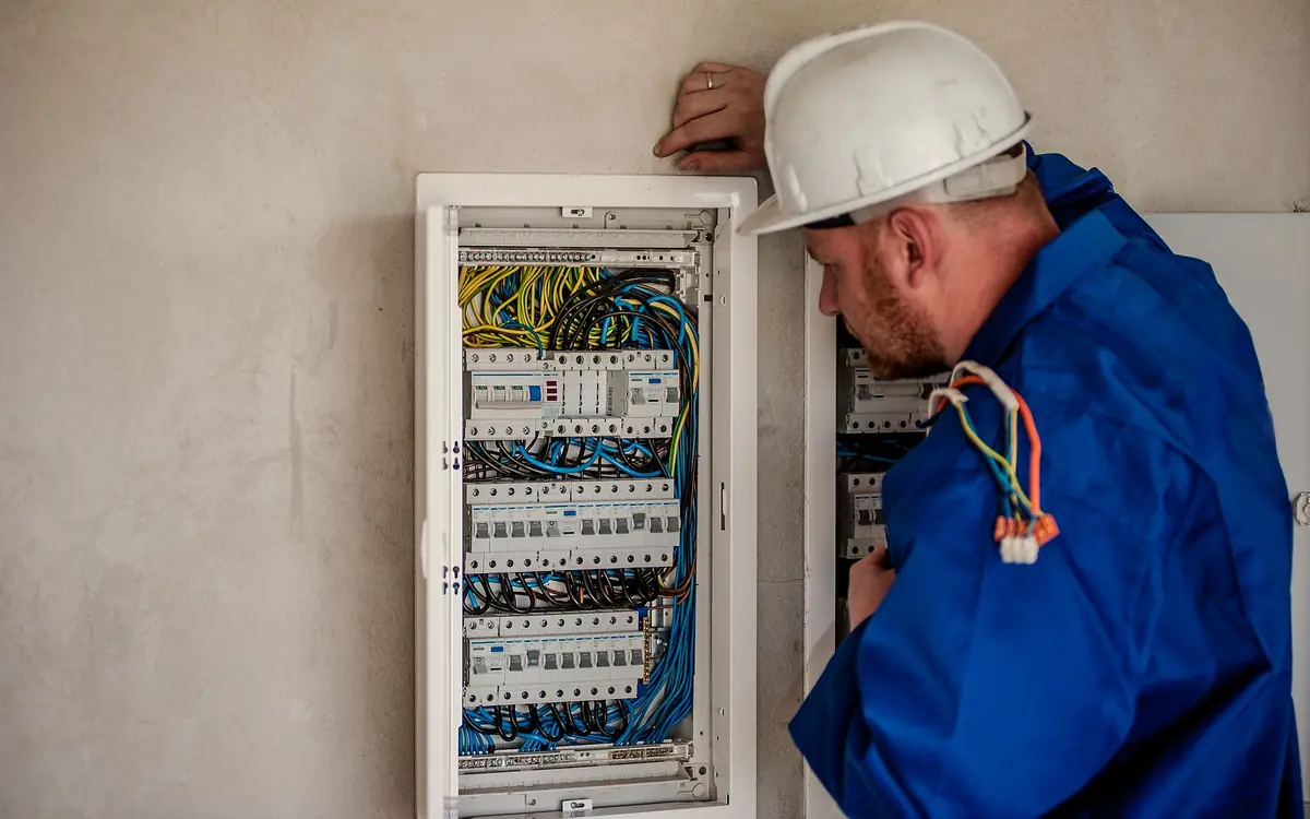
The String Line Across the Lawn Is the Specification
Somebody has already stretched a line from the meter box to the garage door and paced it off at forty metres. That number, not the tool list inside the garage, is what this job turns on. A detached garage rarely asks for much current — a couple of general-power circuits, some lighting, whatever gets wheeled in — and if the building were bolted to the house you would put a small feeder in and think no more about it. Move it forty metres away, bury the connection, and three separate constraints start pulling in different directions on a conductor size that would otherwise have been obvious.
The first is ampacity at the temperature the terminals are rated for, not the temperature the insulation is rated for. The second is voltage drop, which is proportional to length and is therefore the only one of the three that got worse the moment the garage was sited at the bottom of the garden. The third is the one that almost never gets calculated: whether a fault at the far end can push enough current back through the protective conductor to operate the device at the house. Each of those can force a bigger conductor, none of them can make it smaller, and all three have to be settled before anything goes in the ground.
It also matters that this is a feeder to a separate structure and not a very long branch circuit. Under NFPA 70 National Electrical Code that puts it into Article 225, Outside Branch Circuits and Feeders, which limits a structure to one supply except in defined cases and requires a disconnecting means at the structure, readily accessible and near the point of entry. Under BS 7671 Requirements for Electrical Installations it is a distribution circuit feeding a separate consumer unit, with its own disconnection time and its own earthing question. Whichever document is adopted where you are working, the garage ends up with its own board and its own means of isolation, and the run between the two buildings is a thing that must be recorded, because in ten years nobody will remember where it went.
What a Workshop Draws, and When It Draws It
Add up the nameplates in a working garage and you get a number nobody would pay to bury. A welder, a compressor, a table saw, a dust extractor, a car lift, a heater and a kettle will total well past a hundred amps on paper, and they cannot all be running because there is one person in the building and two hands on the job. Feeder sizing has always dealt with this through demand and diversity — Article 220 in the NEC, the diversity allowances in the IET On-Site Guide to BS 7671, the maximum demand tables of AS/NZS 3000 Electrical Installations — and the outbuilding case is where those allowances earn their keep hardest.
The exceptions are the loads that sit at full value for hours, because diversity is an argument about coincidence and those loads do not care. Electric vehicle supply equipment is the obvious one: it is a continuous load, it is sized at 125 percent of its rating in NEC practice, and it is the single change most likely to arrive after the trench is closed. Resistive space heating in a workshop is the same shape of problem — nobody switches a garage heater on for ten minutes in February. Where those two exist or are plausible, they get added at full value on top of a diversified figure for everything else, and that is usually what decides between a sixty amp feed and a hundred.
Motors are the other special case, and they are special in a way that is easy to get backwards. Conductor sizing for a motor branch circuit works from the tabulated full-load current for its horsepower and voltage rather than from the amps printed on the plate, and the tables exist precisely because plate values vary between manufacturers for the same nominal machine. A compressor or a two-post lift at the end of a long soft feeder is also the load that will expose every millivolt of drop, because its starting current is several times its running current and the drop scales with the current of the moment.
Then there is the question the client will not ask and you should. A trench is dug once. The marginal cost of the next conductor size up, while the ground is open and the duct is being bought anyway, is copper and nothing else; the cost of finding out in three years that the feeder cannot take a charger is the whole garden again. Size the feeder for the building the garage is going to become, write down what you assumed, and let the client decline it in writing if they want the smaller number.
Charging equipment is the load that decides this feeder, because it is the one that runs for hours at its rated current — put the charger's continuous rating in and the breaker it returns is the number that has to sit on top of everything else you diversified.
The charger's rated continuous current draw, from its nameplate or manual.
Minimum breaker size
40 A breaker
The breaker size also requires correctly-sized wiring for that circuit (see the Wire Gauge Voltage Drop Calculator) — always have the final circuit installed or verified by a licensed electrician and permitted per local code.
- Minimum required (125% rule)
- 40 A
They open the calculator with your figures already in it
EV Charger Circuit Calculator: 40 A breaker — shown in imperial, US market. The link sets both, so the result they see is the one on your screen.
Add the equipment this sizes
This result is a specification — 40 A breaker — not a quantity. Put the thing it sizes into your project: how many, what you call it, and your supplier’s price.
What this calculation does not cover
- SIZES THE BREAKER, NOT THE SERVICE. The question that stops most EV installations is whether the existing service and panel can carry another continuous load of this size at all, and that is a whole-dwelling load calculation under the code's demand rules — not something a charger's own rating can answer. A panel with a spare double-pole space is not the same as a service with spare capacity.
- Where the service is short, load management is often the answer rather than an upgrade: a listed energy management system, or a charger that sheds when the range is on, lets the circuit be sized to what is actually available. Both are code-recognised and both are far cheaper than a new supply.
- The conductor is a separate calculation. Ampacity at the breaker size, derating for ambient temperature and for conductors sharing a raceway, the termination temperature rating, and voltage drop over what is often a long garage or driveway run all have to be satisfied — a correctly sized breaker on a conductor that fails any of those is the dangerous combination.
- Says nothing about the ground-fault protection, disconnecting means, or outdoor and wet-location requirements that apply to the equipment itself and vary with where it is mounted.
- A receptacle-connected charger and a hardwired one are treated differently by the code, and the choice affects both the protection required and whether the charger may be at the full 125% figure at all.
The Lug Decides Which Column You May Read
Conductor insulation is rated for a temperature and so is every terminal it lands in, and NEC 110.14(C) settles the argument in favour of the lowest-rated part of the connection. In practice that means equipment rated 100 amperes or less, or marked for conductors 14 AWG through 1 AWG, is treated as a 60 degree Celsius termination unless the device or its instructions are marked otherwise. Most modern breakers and panelboard lugs are marked for 75 degrees; plenty of older ones are not, and an unmarked lug is a 60 degree lug. The 90 degree column exists chiefly so you have something to apply correction and adjustment factors to on the way down — it is almost never the number you finish on.
That distinction is worth a size on a garage feeder. Six AWG copper is 55 amperes in the 60 degree column and 65 in the 75 degree column, so the same cable is either short of a sixty amp device or comfortably over it depending on a marking you can only read by taking the dead front off and looking. Check both ends. The breaker at the house and the main lug or main breaker in the garage board are separate answers, and the lower one governs the whole run. UL 486A-486B Standard for Wire Connectors is the document behind the connector side of that relationship, and the torque value in the equipment instructions is part of the listing rather than a suggestion — a lug tightened by feel is the failure that shows up as a browned insulation tail a decade later.
The wiring method carries its own constraint. Everything inside a buried raceway is a wet location from the first winter, whatever the weather was on the day you pulled it, so the conductors have to be listed for wet locations: the dual-rated THHN/THWN-2 that most suppliers stock, or XHHW-2, or a direct-burial cable such as USE-2 where the design is to bury the cable rather than a duct. Plain THHN is a dry-location rating and has no business in a duct that runs under a lawn. In the United Kingdom the equivalent decision is usually made in favour of steel wire armoured cable buried directly, and its ratings come from Appendix 4 of BS 7671 with an installation-method correction that a duct in the ground and a cable in free air do not share.
| Copper conductor | 60 °C column | 75 °C column | 90 °C column |
|---|---|---|---|
| 8 AWG | 40 A | 50 A | 55 A |
| 6 AWG | 55 A | 65 A | 75 A |
| 4 AWG | 70 A | 85 A | 95 A |
| 3 AWG | 85 A | 100 A | 115 A |
| 2 AWG | 95 A | 115 A | 130 A |
| 1 AWG | 110 A | 130 A | 145 A |
| 1/0 AWG | 125 A | 150 A | 170 A |
Run the size you had in mind and read all three columns at once, then discard the two you are not allowed to use — the marking on the lug is what tells you which one that is.
The AWG size of the copper conductor, as printed on the jacket.
Allowable ampacity at 75 °C
25 A
NEC Table 310.16, copper, 75 °C column headline. Table value only — apply the adjustment and correction factors for conduit fill and ambient temperature, and never exceed the 240.4(D) cap on 14, 12 and 10 AWG.
- 60 °C column
- 20 A
- 75 °C column
- 25 A
- 90 °C column
- 30 A
- Maximum overcurrent protection — NEC 240.4(D)
- 20 A
They open the calculator with your figures already in it
Wire Gauge to Amperage Calculator: 25 A — shown in imperial, US market. The link sets both, so the result they see is the one on your screen.
Add the equipment this sizes
This result is a specification — 25 A — not a quantity. Put the thing it sizes into your project: how many, what you call it, and your supplier’s price.
What this calculation does not cover
- Copper only. Aluminium has its own column with materially lower values — using the copper figure on aluminium oversizes the protection, which is the dangerous direction.
- Assumes ambient 30 °C and not more than three current-carrying conductors in the raceway. Outside either condition, the table value must be derated — see the derating calculator.
- The temperature column that governs is the lowest rating in the whole path: conductor, terminations and equipment. Most breakers are listed at 75 °C and much residential equipment at 60 °C.
The reverse lookup an electrician actually performs on an existing installation: the cable is already in the wall and the question is what it may safely be protected at. That is a different task from sizing a new circuit, and it is the one where the small-conductor rule in 240.4(D) most often surprises people.
One Volt Budget, Spent Twice
Voltage drop on this job is not a single calculation, it is a budget with two claimants. The feeder spends some of it getting to the garage, and every branch circuit inside the garage spends the rest getting from the garage board to a socket at the far wall. The familiar three percent for a branch circuit and five percent overall is informative guidance in the NEC rather than an enforceable rule; BS 7671 sets limits in its appendices that must actually be met — three percent for lighting and five percent for other uses on a supply taken from a public distribution network. Either way the arithmetic is the same, and either way a feeder that eats four and a half percent has left nothing for the circuits it exists to supply.
So set the feeder a target rather than a limit. Somewhere around two percent leaves the inside of the garage a workable allowance, and it also leaves room for the load to grow without the drop growing past what the equipment tolerates. It is a design decision, not a code number, and it is the single most useful thing to fix before pricing conductor.
Measure the path, not the lawn. The line somebody paced off is the shortest distance between two buildings and the conductor will not travel it. Add the climb from the house board down to the point where the duct leaves the wall, the offsets around a soil stack and a bay window, the sweeps at each end of the trench, the slack you leave in the duct so the cable is not stretched, and the rise inside the garage to a board that is mounted at chest height. Forty metres of string line lands somewhere near fifty-five metres of conductor on most gardens, and drop is linear in exactly that number.
Drop is also linear in current, which means the worst case is not the average day. It is the moment the welder strikes while the charger is running and the compressor kicks in, and the voltage at the garage board falls furthest exactly when three things want it most. Motors respond to low voltage by drawing more current and running hotter, which makes the drop worse, which is a loop that ends in a tripped overload or a shortened motor.
When the calculation says upsize, the upsize has consequences beyond the price of copper. The protective conductor is increased in proportion under NEC 250.122(B) where the ungrounded conductors are enlarged for voltage drop, which changes the cable you are buying rather than just one core of it. Larger conductors need a larger duct, a longer bending radius inside both enclosures, and lugs that will physically accept them — check that the garage board's main lug takes the size you have arrived at before it is on a reel in the van. Upsizing for drop is the most common reason a feeder outgrows the enclosure that was picked for it.
Enter the one-way route length you measured rather than the distance somebody paced — the field wants the run in one direction and the arithmetic doubles it for you — together with the design current rather than the average, and the percentage in the breakdown is the share of the budget the feeder has taken before the garage has spent anything. Its gauge list and its current field both run past an ordinary garage feed, so a larger subpanel feeder goes through the same page.
Copper, or aluminum — the metal printed on the jacket (CU or AL).
The size printed on the jacket: an AWG number up to 4/0, then kcmil.
Single phase — including a 240 V circuit and DC — or a balanced three-phase circuit.
The distance from the panel to the load, one direction only.
The expected current draw of the load in amps.
The nominal circuit voltage — line to line for three phase.
Voltage drop
1.936 V
- Voltage drop
- 1.61 %
- Voltage at the load
- 118.06 V
- K constant, Ω·cmil per ft
- 12.9
- Conductor area, circular mils
- 6,530
They open the calculator with your figures already in it
Wire Gauge Voltage Drop Calculator (Copper or Aluminum, AWG to 1,000 kcmil): 1.94 V — shown in imperial, US market. The link sets both, so the result they see is the one on your screen.
Add the equipment this sizes
This result is a specification — 1.936 V — not a quantity. Put the thing it sizes into your project: how many, what you call it, and your supplier’s price.
What this calculation does not cover
- VOLTAGE DROP IS NOT AMPACITY, and the two are different questions with different answers. A conductor can stay inside the 3% suggestion and still be too small to carry the current without overheating, and it can be thermally adequate and still drop too much over a long run. Both checks have to be made, and only one of them is made here.
- The K constants are DC resistance at 75 °C (167 °F) for uncoated copper and for aluminum, the basis of NEC Chapter 9 Table 8. The table's size-by-size resistances differ from the single constant by a percent or so either way, and the table is not reproduced here. A conductor running cooler drops a little less and one at a 90 °C (194 °F) rating a little more; tinned (coated) copper has its own, slightly higher resistance.
- Treats the circuit as resistive, which is close for lighting, heating and most branch circuits. On a large AC feeder, and above all one in steel conduit feeding an inductive load, the conductor's reactance adds to the drop and the power factor matters; Table 9 of the same chapter carries the AC figures and is not reproduced here.
- Three phase assumes a balanced load and gives the drop between lines. A single-phase load taken from one line to neutral of a three-phase supply is a single-phase circuit: choose single phase and the line-to-neutral voltage.
- Aluminum conductors need terminations and devices listed for them; the code does not let dissimilar metals be joined except in a device listed for the purpose. Nothing here checks a termination, a lug or a splice.
- The 3% and 5% figures are suggestions in the code's informational notes rather than requirements, though a local amendment, an equipment maker's instructions or a specification can make a tighter figure binding.
A Fault at the Far End Has to Get Home
Here is the constraint that separates a competent outbuilding feed from a dangerous one. When a live conductor touches the metal frame of a machine in the garage, the current that operates the protective device has to return to the source through a conductor, and the earth beneath the garden is not that conductor. NEC 250.4(A)(5) says so explicitly: the earth shall not be considered an effective ground-fault current path. The arithmetic is Ohm's law and it is brutal. A driven rod that achieves 25 ohms — a respectable figure in ordinary soil — offers 240 volts divided by 25 ohms, which is under ten amperes. A sixty ampere breaker will sit and watch that indefinitely while the machine frame stays live.
Which is why a feeder to a detached structure runs with an equipment grounding conductor pulled alongside the live conductors and the neutral, and why the neutral is not re-bonded to earth at the garage. NEC editions from 2008 onward removed the old permission to use the grounded conductor as the fault path at a separate building, so the modern arrangement is four wires to a three-wire supply: two ungrounded, one grounded, one equipment grounding conductor, with the bonding screw or strap taken out of the garage board and the neutral bar isolated from the enclosure. The garage still gets a grounding electrode of its own under NEC 250.32 — a rod, or the reinforcement of its slab where that qualifies as a concrete-encased electrode — but that electrode is a reference and a surge path, not a fault path, and it never substitutes for the conductor.
The British framing gets to the same place by a different route and with a number attached. Automatic disconnection of supply requires the earth fault loop impedance at the point of the fault to be low enough that the device operates within the disconnection time — commonly 0.4 seconds for a final circuit and 5 seconds for a distribution circuit on a TN system. A Type B miniature circuit breaker needs somewhere between three and five times its rated current to trip magnetically, and a Type C between five and ten times, so a 40 ampere Type B wants roughly 200 amperes of fault current before it will operate quickly. Fifty-five metres of feeder with an undersized protective conductor adds resistance to both legs of that loop, and the adiabatic check in Section 543 of BS 7671 then has to confirm that the protective conductor survives the current for as long as it takes to clear.
The earthing arrangement itself is a separate decision in the United Kingdom and one worth taking advice on rather than assuming. Exporting a PME earth to an outbuilding is constrained by the distributor's conditions and by the Electricity Safety, Quality and Continuity Regulations 2002, and the common alternative is to earth the garage as a TT island with its own electrode and residual current protection, which changes the disconnection argument from impedance to residual current. Buried cable in a garden attracts a 30 milliampere residual current device in any case, and the NEC reaches the same protective outcome for people through the ground-fault circuit-interrupter requirements that cover garage and outdoor receptacles.
This is the calculation that makes the point: enter the supply voltage and the resistance of the path you were hoping would clear the fault, and read the current it will actually pass.
The voltage across the circuit or component.
The resistance of the circuit or component, in ohms.
Current
3 A (current)
- Power
- 36 W
- Voltage
- 12 V
- Resistance
- 4 Ω
They open the calculator with your figures already in it
Ohm's Law Calculator: 3 A (current) — shown in imperial, US market. The link sets both, so the result they see is the one on your screen.
Add the equipment this sizes
This result is a specification — 3 A (current) — not a quantity. Put the thing it sizes into your project: how many, what you call it, and your supplier’s price.
What this calculation does not cover
- This is not a load calculation and not a circuit design. It returns the current a fixed resistance draws at a given voltage, and says nothing about conductor ampacity, derating for ambient temperature or conduit fill, overcurrent device sizing, or whether the circuit is compliant.
- The model assumes a purely resistive load. On an AC circuit with motors, transformers, LED drivers or switch-mode supplies the current is set by impedance rather than plain resistance, and the power figure is apparent power in volt-amps, not watts, wherever the power factor is below 1.
- Resistance is taken as a fixed number. Conductor, element and filament resistance rise with temperature and terminations add their own, so a cold ohmmeter reading understates the operating resistance and the current shown will run high against what the circuit actually draws hot.
- Nothing is subtracted for the supply run. The voltage you enter is assumed to appear across the resistance itself, so on a long circuit the load sees less than that and draws proportionally less current than the figure here.
- The calculator prints whatever the arithmetic gives, including the fault-level current a very low resistance produces at mains voltage. It is not a short-circuit, interrupting-rating or arc-flash study, and it does not check that the current or power it reports is survivable for the conductors, the device or the person working on it.
The Trench, and What Is Already In It
Before anything else, find out what is already under the lawn. A garden between a house and a garage is a good place to find a gas service, a water main, a soil drain, a telecom duct and an irrigation line, none of which are on a drawing and at least one of which is shallower than anybody expects. HSE guidance HSG47, Avoiding Danger from Underground Services, sets out the sequence — plans, then a locator, then careful hand digging near anything found — and it is the right sequence whether or not you are working under UK law. Where a locate service exists, use it, and note that a private garden run between two buildings is exactly the case such services do not have records for.
Depth is set by the wiring method and by what is on top, not by preference. NEC Table 300.5 gives different minimum cover for different methods and locations: direct-buried cable deepest at 600 mm, rigid nonmetallic conduit at 450 mm, rigid metal conduit shallowest at 150 mm, with a reduced row for a residential 120 volt branch circuit at 20 amperes with residual protection, and different figures again under a driveway or a building. Read the row for your method in the edition your jurisdiction has actually adopted. BS 7671 prescribes no single depth in Section 522, requiring instead that a buried cable be of a type suitable for the duty, at sufficient depth to avoid damage, and marked — with NJUG Volume 4 giving the positioning and colour coding practice the utilities themselves work to. Frost depth, tree roots and the route of a future patio all argue for going deeper than the minimum rather than exactly to it.
Trench safety scales with depth faster than people expect, and the point at which a garden trench becomes an excavation with rules attached is lower than the point at which it looks dangerous. OSHA 29 CFR 1926 Subpart P, Excavations, governs that in the United States: spoil set back from the edge, a means of getting out, and a protective system where the depth demands one. A collapse in a metre and a half of wet clay is enough to kill someone kneeling in it, and a domestic job is exactly where the discipline slips.
- Establish and mark the existing services across the whole route before the first spit is turned, then hand dig within the safe distance of anything located.
- Set the route to avoid tree root plates, soakaways and the footprint of any structure the client has mentioned wanting, and record where you moved it to.
- Excavate to a consistent formation level, keeping spoil back from the edge and off the reinstatement material.
- Bed the duct on screened fill, lay it with long sweeps rather than elbows, and leave a draw rope in it whether or not you intend to pull that day.
- Bring the surround up over the duct by hand, lay the warning tape well above it rather than on it, and photograph the open trench with a tape measure in shot.
- Backfill in lifts and compact each one, then reinstate the surface proud of finished level to allow for the settlement that is coming anyway.
What is actually in the trench
- Reinstated turf and topsoil — the only part of the job the client will ever inspect, and the part that reads as a settled scar across the lawn all winter if the fill below it went in loose Topsoil Calculator
- Compacted backfill — returned in lifts and compacted as it goes, because excavated soil bulks on the way out and a trench filled in one push becomes a trench-shaped hollow by spring Trench Excavation & Backfill Volume Calculator
- Warning tape — the only warning the next person with a spade is going to get, and worth nothing at all if it is laid on the duct instead of well above it
- Sand surround — screened material with no sharp stone in it, brought up around and over the duct so that nothing point-loads it while the backfill above is being compacted
- Duct and feeder conductors — sized for the pull and the fill rather than for the copper alone, and a wet location on the inside from its first winter whatever the weather was on pull day Conduit Fill Calculator
- Bedding — a level bed of the same fine material so the duct is carried along its whole length rather than bridging between two stones with a span in between
- Undisturbed trench floor — cut to a consistent grade with no sumps left in it, and battered or supported wherever the depth and the ground condition call for it Trench Sloping & Excavation Width Calculator
Excavated ground does not go back in the hole it came out of — the volume you dug and the volume of imported surround are different numbers, and this is where the difference gets ordered.
The total length of the trench.
The width of the trench.
The depth of the trench.
The outer diameter of the pipe being laid; 0 for a trench with no pipe.
Depth of bedding material under the pipe; 0 if the pipe sits on the trench bottom.
Depth of the same bedding material over the top of the pipe; 0 for none.
Extra loose material needed to achieve full compaction in the void.
Loose backfill material needed
50.9 yd³
Assumes the excavated soil itself isn't reused as backfill (e.g. importing clean granular fill) — if reusing native soil, account for its own swell factor separately.
- Excavation volume (the depth entered)
- 48.89 yd³
- Pipe volume (subtracted)
- 4.6 yd³
- Compacted backfill void
- 44.29 yd³
They open the calculator with your figures already in it
Trench Excavation & Backfill Volume Calculator: 50.93 yd³ — shown in imperial, US market. The link sets both, so the result they see is the one on your screen.
Estimated cost — your price
This site holds no price list for this material — local prices vary too much to publish honestly. Enter your supplier's price and the result is costed with it.
The pipe is drawn to scale inside the trench. Backfill is everything else in the section, which is why the pipe diameter changes the answer at all.
What this calculation does not cover
- The trench is modelled as a plain rectangular prism — vertical faces, one width and one depth over the whole run. Battered or benched sides, the extra width a trench box needs, over-break outside the drawn line, and a bottom that falls with the pipe's gradient are all outside it. A run cut back to a safe slope holds considerably more than this figure, and the shortfall rises with the square of the depth rather than in proportion to it.
- This is a quantity take-off, not an excavation safety assessment. Nothing here classifies the soil, checks the depth against sloping, benching or shoring requirements, or sizes a protective system — that comes from a competent person on site, and past the depths the rules set, from an engineer.
- Only the single pipe you enter is deducted. A second pipe or duct sharing the trench, cable bundles, manholes, chambers, valve boxes, thrust blocks and concrete surround all displace backfill and are not subtracted. No check is made that the pipe fits the trench you described either: where its volume exceeds the excavation, the answer is floored at zero rather than reported as impossible geometry.
- At most two materials: a bedding and surround zone when you enter a bed or a cover, and one backfill above it at one flat percentage. The bedding row is an in-place volume across the full trench width, capped at the trench depth, with no compaction or waste allowance, so add your own for a graded bedding that is compacted. Marker tape or protective tiles, and the sub-base, blacktop or topsoil at the surface are further materials in further thicknesses and are not split out. The percentage is a loose-volume allowance on the backfill and nothing else — it is not a density or Proctor specification, and it says nothing about lift thickness or how many passes the plant makes.
- Nothing is said about the spoil. The excavation row is a bank volume measured in place, not the loose volume that leaves in the truck, and the calculation does not judge whether the arisings can go back, how much of the void they would fill, or what has to be carted away. Rock, groundwater and dewatering, and over-excavation to remove unsuitable ground are all excluded.
Pulling It Through
A long duct pull fails at the bends, not along the straights. Tension builds through friction on every straight section and then multiplies through each change of direction, so two ninety degree elbows in an otherwise easy run can turn a comfortable pull into one that stretches the conductor or strips the jacket. Use long sweeps, keep the total angular content of the run down, and put a pit or a pull point in wherever the geometry demands it rather than trusting to lubricant and effort. Cable-pulling lubricant is not optional on a long feeder, and the manufacturer's guidance — the Southwire Power Cable Installation Guide is the usual reference for the tension and sidewall pressure arithmetic — states a maximum tension for the conductor and a maximum sidewall bearing pressure at a bend, both of which are exceedable by hand with a rope and two willing people.
Feed from the end with the awkward bends and pull from the end with the room. Let the conductors come off the reel in the direction the reel wants to turn, keep them off the ground and out of the spoil, and pull all of the conductors at once including the protective one — the equipment grounding conductor belongs in the same raceway as the conductors it protects, and pulling it separately later is both a nuisance and a mistake if it ends up in another route. Leave enough tail at each end to dress the conductors properly into the boards, because a feeder cut short at the garage end is a joint in a box you did not plan.
Cable weight, run length and the friction of the duct give you a straight-run tension figure to sanity-check before somebody puts a winch on it — the bends push the real number above this one.
The cable's weight per unit length, including its jacket and any armor.
The total length of the straight conduit run being pulled.
The friction between the cable jacket and the conduit interior.
Estimated pulling tension
67 lbf
This covers a STRAIGHT run only — pulls with bends require adding capstan-equation tension multipliers for each bend, and the calculated tension must be checked against the cable manufacturer's maximum allowable pulling tension (often based on conductor cross-section) before pulling. Consult a qualified installer for multi-bend or long/complex pulls.
- Tension in kgf
- 30.18 kgf
They open the calculator with your figures already in it
Cable Pulling Tension Calculator (Straight Run): 66.52 lbf — shown in imperial, US market. The link sets both, so the result they see is the one on your screen.
Add the equipment this sizes
This result is a specification — 67 lbf — not a quantity. Put the thing it sizes into your project: how many, what you call it, and your supplier’s price.
What this calculation does not cover
- Jamming and clearance are failure modes that are not forces, so no tension figure predicts them. Three cables of similar diameter can wedge side by side going through a bend when the conduit's inside diameter falls in a narrow band near three times the cable diameter, and the pull locks solid at a tension the winch will happily exceed and the cable will not survive. A single large conductor has the mirror problem — it needs a minimum clearance to the conduit wall through every bend. Check the geometry of what is going in before trusting any number here.
- Cold changes the pull and can end it. Jacket and insulation stiffen as the temperature drops, so the same cable in the same conduit pulls appreciably harder in winter than the friction coefficient above suggests, and most cables carry a minimum installation temperature below which the jacket cracks rather than bends. Neither the friction figure nor the weight in this calculation moves with temperature; warming the reel before the pull does more than either of them.
- This is what the conduit costs you. The reel adds its own before the cable reaches the conduit at all — a heavy drum with a stiff brake, a feed that is not squared up with the conduit mouth, or a sheave set at the wrong angle each contribute back-tension and an extra effective bend right at the head of the run, and being at the head, everything downstream multiplies it.
Closing Out the Garage End
The garage board is where every decision made in the trench becomes visible. It needs a means of isolation at the structure, a neutral bar floating clear of the enclosure with the bonding link removed, an earth bar bonded to the enclosure and carrying both the incoming protective conductor and the electrode conductor, and a directory that states what feeds it and where that feed is isolated. Site it where the working space required by NEC 110.26 actually exists — around 900 mm of depth, 750 mm of width and 2 m of headroom for the ordinary case — which in a real garage means not behind where the car parks, not above the bench, and not in the corner that will be racking within a year.
Seal the raceway where it enters the building. A duct that runs from a cold trench into a warm garage is a condenser, and an unsealed one delivers water into the bottom of the board over a few seasons; the NEC's raceway sealing requirement in Article 300 exists for exactly that mechanism. Where the duct rises out of the ground into sunlight, rigid PVC expands and contracts enough over a season to need an expansion fitting, and Article 352 covers that for nonmetallic conduit. Neither of these is expensive at first fix and both are miserable to retrofit.
Look for metallic paths running in parallel with your feeder. A steel water pipe, a gas line or a telecom cable running between the two buildings creates a second route between the earthing systems, which is capable of carrying neutral current and of putting a difference of potential across two things somebody can touch at once. That is a bonding question with a real answer, and the answer depends on the earthing arrangement, so it belongs on the design rather than in a discovery at second fix. NECA 1 Standard for Good Workmanship in Electrical Construction is a reasonable yardstick for the standard of the terminations and supports you leave behind.
Then write it down. Photograph the open trench with a tape in it against two fixed features of the property, record the route on a sketch that goes to the client, label both boards with the size and type of the feeder and the fact that its neutral is not bonded at the garage, and test and record the loop impedance or the fault path continuity at the far end rather than assuming it from the calculation. Everything else on this job is buried within a day. The record is the only part of it that is still accessible to the next person, and on a private garden run between two buildings there is no utility drawing that will ever fill in the gap.
Fix these before the digger arrives
Everything on this list is cheap while the ground is open and expensive afterwards. Work down it in order; each line can only push the conductor size up, never down.
- Diversified demand, plus continuous loads at full value — Charging equipment and resistive heating do not diversify — add them on top of the diversified figure rather than into it.
- Termination temperature marking at both boards — The lower of the house breaker lug and the garage main lug decides which ampacity column the whole feeder may use.
- Measured conductor path, not the paced distance — Include both risers, every offset, the sweeps at each end of the trench and the slack left in the duct.
- Feeder share of the voltage drop budget, set as a target — Leave the branch circuits inside the garage a workable allowance instead of spending the whole five percent on the run.
- Four conductors: two live, neutral, and a protective conductor — Pulled in the same duct, with the bonding link removed at the garage board and the neutral bar isolated.
- Duct, surround, warning tape and reinstatement material — Order the surround as imported screened fill; excavated spoil bulks and rarely goes back as the bedding layer.
Opens the calculators above on one screen with the dimensions from this article already filled in. Quantities only — this site publishes no price list, because local prices vary too much to publish honestly.