
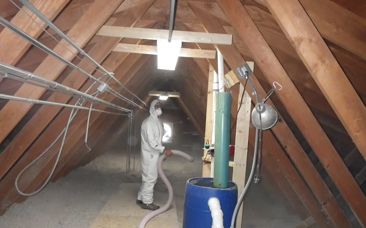
Eighteen Months Later, Through a Finished Floor
The call that makes this job worth doing properly does not come from the site. It comes from a validation monitor left in a finished house eighteen months after handover, reading a gas concentration the design said the building would never see. By then the membrane is under a hundred and fifty millimetres of concrete, a screed and somebody's oak flooring. What is left is a fan, a riser core-drilled through the slab, and a maintenance obligation running for the life of the building — paid for by whoever owns it, not by whoever laid the sheet.
A gas-resistant membrane is not a damp-proof membrane that has been asked to try harder. A DPM holds back liquid water and water vapour, and its performance is a permeance measured by methods such as ASTM E96/E96M. A ground gas barrier holds back bulk flow — gas driven into the building by barometric swings, by wind pressure on the facade, by the stack effect of a heated house — and, behind that, the slow diffusion of gases the water-vapour test says nothing about. Molecular size is not what separates the two: radon, methane and carbon dioxide are all bulkier than a water molecule. What differs is how readily each dissolves into the polymer and travels through it, which is why gas transmission is a separately measured property, by methods such as ISO 15105-1, and separately declared. A polythene sheet with a damp-proofing certificate is not automatically anything else.
The specification is not the membrane rep's to write, and it is certainly not the slab gang's. In the UK it comes out of the site investigation: borehole gas monitoring read against the gas screening values in CIRIA C665, which places the site in one of the characteristic situations of BS 8485, which in turn sets how much protection the slab, the ventilation layer and the membrane have to contribute between them. Radon runs on its own track, where BRE Report BR 211 and the national radon potential mapping decide whether a site needs basic protection — a radon-proof barrier across the whole footprint — or full protection, which adds a means of depressurising the ground beneath it. In the United States the equivalent chain runs from the EPA Map of Radon Zones through the radon control methods appendix of the International Residential Code, where the jurisdiction has adopted it, and through ANSI/AARST CC-1000 for new construction. Whichever regime applies, the answer arrives as a document before the dig, and the roll you order has to match it.
Everything Under the Slab, in the Order It Goes Down
Six things get bought here, in five different units, and every interface between them is somebody's hold point. Formation is bought as compaction rather than as material. The venting blanket is bought by the tonne. Blinding is a skim. The membrane is bought by the roll and installed by the square metre of covered surface, which is not the same number as the floor. The protection layer comes by the roll or the sheet. The slab arrives by the cubic metre on a truck that will not wait. Get the sequence wrong on any one and the layer above turns up before the layer below has been signed off.
Membrane quantity is where estimates go wrong first, because the plan area is the smallest number in the sum. You are covering the floor, plus the perimeter upstand — its run is the internal perimeter and its height is however far up the wall the detail carries it — plus every lap, plus the offcuts eaten by top hats and internal corners, plus the sheet you will cut up to patch what a boot puts through it on the third day. Order the extra roll. It costs less than half an hour of a crew standing still because there is not enough material to finish a bay before the tape run is broken.
What sits between the dirt and the finished floor
- Ground-bearing slab — the operation that makes everything beneath it permanent, ordered by the cubic metre and placed in one continuous run over an assembly nobody can reopen Concrete Calculator
- Protection layer — geotextile, board or sacrificial sheet taking the boots, barrow wheels and chair feet that would otherwise land straight on the barrier Foundation Waterproofing Protection Board Calculator
- Gas-resistant membrane — the barrier itself, bought by covered surface rather than plan area because the perimeter upstand and every lap are part of the sheet you pay for Vapor Barrier Calculator
- Sand blinding — a regulating skim over the stone so the sharp arrises selected for the venting layer are not the first thing the membrane meets
- Granular venting blanket — clean single-sized stone whose value is the void between the particles, ordered by the tonne against a compacted depth and ruined by fines Gravel Base Layer Tonnage Calculator
- Compacted formation — bought as a compaction result rather than as a material, and the surface every layer above it inherits its flatness from Standard/Modified Proctor Compaction Percentage Calculator
Roll count is the first number the supplier asks for, so put the covered surface — floor plus upstand, not plan area — through it while the sheet is still a line on an order. It answers in standard 6-mil poly rolls with a waste allowance already inside it, so treat that as the baseline and rescale against the roll width your gas membrane supplier actually quotes.
The total crawlspace floor or basement wall area to cover.
Sheet spent where seams overlap before they are taped.
Vapor barrier rolls needed
2 rolls
- Area to cover (with overlap allowance)
- 1,188 sq ft
They open the calculator with your figures already in it
Vapor Barrier Calculator: 2 rolls — shown in imperial, US market. The link sets both, so the result they see is the one on your screen.
Estimated cost — your price
This site holds no price list for this material — local prices vary too much to publish honestly. Enter your supplier's price and the result is costed with it.
What this calculation does not cover
- The roll is fixed at a 10 ft x 100 ft (3 m x 30 m), 1,000 sq ft (93 m²) sheet. The calculator never asks what you are buying, so a 12, 16 or 20 ft wide roll, a 50 ft roll, or a reinforced 10-20 mil barrier will not divide into this count. Take the area figure from the breakdown and divide it by your own product's stated coverage.
- The overlap allowance is for flat-plane seams only. Nothing is added for turning the sheet up the foundation wall, wrapping piers and columns, sealing around penetrations, or the off-cuts an irregular crawlspace footprint produces. Measure and add those separately.
- Only the sheet is counted. Seam tape, mastic, mechanical fasteners and termination bar are not in this estimate.
- This is a quantity take-off, not a vapour-control design. It says nothing about the permeance, thickness or puncture class the barrier has to meet, or which face of the insulation it belongs on. In a cold store or an unvented crawlspace the wrong side traps moisture inside the assembly no matter how many rolls you order.
- It is not a radon or ground-gas membrane specification. Those are designed, jointed and verified systems with their own material, welding and testing requirements, and a 6-mil poly roll count does not substitute for one.
A Blanket That Has to Breathe
The stone under the membrane is not sub-base. It is a gas collection layer, and its entire value is the void between the particles. Clean, single-sized, angular coarse aggregate holds that void; as-dug gravel with fines in it does not, and a venting layer that the muck-away lorry has driven across has stopped being a venting layer without anybody writing it down. The radon control methods appendix of the International Residential Code names a gas-permeable layer of clean coarse aggregate at a stated minimum depth — four inches, in the jurisdictions that have adopted it — and BS 8485 treats a designed ventilation layer as part of the protection the building has to add up to, not as an optional extra a value engineer can delete.
A venting blanket with no outlet is drainage stone with delusions. It has to connect to something: a perimeter vent trench with periscope or ventilator terminals above ground, slotted pipe laid within the stone and run out to open air, or a capped riser waiting to be turned into an active system. Decide which before the stone is tipped, because that pipework goes in with the stone and not afterwards.
Two separation layers earn their keep at this level and they do opposite jobs. Below the stone, a separation geotextile stops the formation pumping fines up into the void under construction traffic. Above the stone, a sand blinding or a fabric stops the sharp arrises of the same aggregate doing to your membrane exactly what they were selected to do to everything else. Leaving the upper one out is the most common reason a barrier fails an integrity test in a place nobody ever walked.
Order it by weight, because that is how the quarry sells it, and work it out from compacted depth and a density you have asked for rather than assumed. Well-graded crushed base and clean single-sized stone do not weigh the same per cubic metre, and the second is the one you want here.
The blanket is specified as a compacted depth over a footprint and delivered as tonnes on a weighbridge ticket, so convert between the two before the first lorry is booked — and enter the density of the clean single-sized stone you actually ordered, not the well-graded base you would put under a road.
The total area to be covered with gravel base.
The target compacted thickness of the base layer.
The in-place density of the base once it is compacted.
Gravel base needed
73.8 tons
Actual density varies by material gradation and compaction — confirm with your supplier's specific product density for a precise order quantity.
- Volume
- 39.81 yd³
- Equivalent in US (short) tons
- 73.82 tons
They open the calculator with your figures already in it
Gravel Base Layer Tonnage Calculator: 73.82 tons — shown in imperial, US market. The link sets both, so the result they see is the one on your screen.
Estimated cost — your price
This site holds no price list for this material — local prices vary too much to publish honestly. Enter your supplier's price and the result is costed with it.
What this calculation does not cover
- This is a take-off, not a pavement design. It multiplies out whatever compacted thickness you enter; nothing here derives that depth from traffic loading, subgrade strength, drainage or frost depth, which come from a pavement design or your local road authority's standard.
- Geometry is a flat plan area at one uniform depth. Crown and cross-fall, a formation that steps between thicknesses, a dig that deepens where the subgrade was soft, and edge thickening or haunching at the perimeter all fall outside area x thickness.
- No waste, spillage or subgrade-loss allowance is applied. The figure is the exact in-place mass, so stone lost into a soft or uneven formation, over-excavation, haul and spread losses, and the tail end of a part-load all sit on top of it.
- The density field is an in-place compacted density. A supplier's loose bulk density and a weighbridge ticket carrying free moisture are different quantities, and substituting either moves the tonnage: the wetter the delivered material, the less dry stone a given delivered weight puts on the ground.
- It covers one layer of one material. A base and sub-base of different gradations, a bedding or blinding course, and the geotextile or separation membrane between stone and subgrade are not counted here.
Laps, and What They Cost at Handover
A taped lap is three things going right at once: a lap wide enough that the tape sits in the middle of it with sheet either side, a substrate clean and dry enough for the adhesive to wet out, and a temperature above whatever minimum the tape manufacturer prints. Miss any one of the three and the joint looks perfect and holds nothing. Double-sided butyl inside the lap with a capping tape over the exposed edge is the normal detail; a single strip stuck across the top of two loose sheets is not a seam, it is a dressing.
Welded seams change the argument, because a weld can be tested. A hot wedge machine run along a lap leaves two parallel welds with an air channel between them; that channel can be sealed at one end, pressurised at the other and watched for pressure loss over a stated period, which is the procedure in ASTM D5820. Single welds, extrusion welds and patches take a vacuum chamber instead, per ASTM D5641, and where the specification calls for destructive proof, a coupon cut from the seam is peeled and sheared to ASTM D6392. Trial welds at the start of each shift, after any machine change and whenever the weather turns are not a formality — a wedge temperature that suited a still morning will burn through the sheet by mid-afternoon.
Welding also needs something firm and flat beneath the lap. A wedge machine run over soft sand blinding lets the lap deflect away from the wedge, so the detail either brings the seams onto a firm strip or the job accepts taped seams and the testing regime that goes with them. That is a specification decision, not one for the operative who turned up with whichever machine was on the van.
Set the sheets out so the laps face the way the pour will travel over them, stagger end laps between adjacent runs instead of lining them up into a continuous cross joint, and never leave four sheet corners meeting at a point. Cross laps take extra tape and extra attention because they are the one place four edges have to be sealed to each other.
Then count the tape. The field seams are the easy part: sheets across the width, one seam fewer than the number of sheets, each running the length of the bay. What catches people out is everything else — the cross laps, the perimeter seal, every top hat, and the patch kit. Order the field figure, then order again for the details, because tape is the item a crew runs out of at four in the afternoon with a bay open.
Field seams are pure geometry — roll width against bay width, times the run — and this settles that part before the order goes in. It counts the straight overlap seams only, which is the honest scope: cross laps, top hats and the perimeter seal come off your own detail count on top of it.
SettingsSettings for this calculation
Waste is set to 5% by hand. Pick a tier above to replace it, or keep your own figure.
The overall width of the slab area being covered by the vapor barrier.
The width of a single vapor barrier roll or sheet.
The overall length of the slab area, running the direction of each seam.
Extra tape to allow for overlaps, patches, and cut waste.
Seam tape needed
154.3 ft
- Number of seams
- 3
They open the calculator with your figures already in it
Under-Slab Vapor Barrier Seam Tape Calculator: 154 ft — shown in imperial, US market. The link sets both, so the result they see is the one on your screen.
Estimated cost — your price
This site holds no price list for this material — local prices vary too much to publish honestly. Enter your supplier's price and the result is costed with it.
What this calculation does not cover
- The sheet count divides the slab width by the full roll width, so nothing is deducted for the side lap where adjacent sheets overlap each other. Laps are typically specified somewhere between 150 mm (6 in) and 300 mm (12 in) depending on the barrier manufacturer and the project specification, and once that is taken off the effective coverage of each sheet a wide slab can need one more sheet, and one more seam, than this calculation reports. Enter the lapped coverage width rather than the printed roll width if you want the lap counted.
- Only the longitudinal seams between sheets laid side by side are counted, and each is taken as running the full slab length in one unbroken run. If the roll is shorter than the slab, every run also carries an end lap partway along it, and there is no roll-length input here, so that transverse tape is absent from the total.
- The figure is seam tape between sheets and nothing else. Sealing the barrier to the footing, the foundation wall or the slab edge, and taping around pipes, conduit, column bases and other penetrations are all excluded and have to be estimated separately. On the default 20 m by 15 m slab the perimeter alone is 70 m against the 47.25 m of seam tape returned, so the excluded work can be the larger quantity.
- Which dimension you enter as the width decides the answer, and the calculator does not compare the two lay directions for you. Running 6.1 m sheets across the 20 m side of a 20 m by 15 m slab gives three seams and 47.25 m of tape, while running them across the 15 m side gives two seams and 42 m. The geometry also assumes one plain rectangle, so an L-shaped or stepped slab has to be broken into rectangles and the results added.
Every Service Is a Hole You Agreed to Make
Penetrations are where gas protection is won or lost, because everything else on this job is a flat plane and a penetration is a three-dimensional joint made by hand, in a trench, by somebody who wants to go home. The failure is rarely dramatic: a collar clamped over a pipe that still has mud on it, a tape run that stops short at the back where nobody could reach, a sleeve trimmed too short to take the clamp.
Use preformed top hats. One cut from offcuts on site has no bonded corner, and the corner is the part that fails. The unit arrives as a flange and a sleeve; the flange bonds to the membrane exactly like a lap, with the same tape and the same width of contact, and the sleeve seals to the pipe with a mastic band and a mechanical clamp above it. Sleeve length matters — it has to reach past the clamp and still finish clear of where the slab surface will be — and the manufacturer states what that length is.
Everything you can do to reduce the count, do before the membrane arrives. Group services into one duct rather than bringing four pipes up through four holes. Get the drainage, the water main, the incoming electricity and the ducting stubbed and braced at final level before a roll is unwrapped, because a service pushed up through a laid membrane is a cut and not a penetration. Bring pipes up perpendicular; a raking service turns a circular top hat into an ellipse it was never made for. And keep penetrations out of the perimeter upstand altogether — the sheet is already turning a corner there and does not need a second geometry to negotiate at the same time.
- Confirm the service is at final level and braced, with the pipe clean and dry above the collar line.
- Cut the membrane to the pipe diameter rather than oversize — the flange is the seal, but a wide hole leaves an unsupported edge inside it.
- Slide the top hat down over the pipe and bed its flange to the membrane at the full lap width, working from the far side back towards yourself.
- Cap the flange edge the whole way round, including the run behind the pipe that you cannot see from where you are kneeling.
- Seal the sleeve to the pipe with the mastic band, clamp above the band, and check the sleeve still finishes clear of slab level.
- Photograph it with the service identifiable and a scale in frame, before anything covers it.
The Tuck at the Perimeter
A membrane that stops at the edge of the slab has protected the middle of the room. Ground gas does not enter through the middle of the room. It enters at the junction between floor and wall, through the cavity, up the inner leg and out at the skirting — which is why the perimeter is the first thing a verifier walks to.
Continuity means the floor membrane and the wall damp-proof course become one barrier, lapped so the joint is held by compression and adhesive together, and lapped in the direction the detail drawing shows rather than whichever way the sheet happened to fall. On a cavity wall the upstand carries up the inner leg to the DPC and bonds to it; where a cavity tray is involved, the tray is part of the same continuous line. Seal the upstand to the blockwork with the manufacturer's mastic and hold it mechanically, because tape alone on dusty fair-faced block is a joint with about one season in it.
The perimeter insulation strip runs the same line, and the sequence between the two is a decision rather than an accident. Rigid foam is not a bonding substrate for a gas seal unless the membrane manufacturer says it is, so in most details the upstand goes to the masonry and the insulation sits inboard of it. Whichever way the detail runs, both quantities come off the same measurement — the internal perimeter — so take them off in one sitting instead of measuring the same line twice on two different days.
You have just measured the internal perimeter for the upstand, and the edge insulation strip is bought off that same run as a board count rather than an area. Settle it now so the two lines on the order agree with each other.
The total length of the foundation perimeter to be insulated.
The length of a single rigid foam board as sold.
Foam boards needed
17 boards
They open the calculator with your figures already in it
Under-Slab Perimeter Rigid Foam Board Calculator: 17 boards — shown in imperial, US market. The link sets both, so the result they see is the one on your screen.
Estimated cost — your price
This site holds no price list for this material — local prices vary too much to publish honestly. Enter your supplier's price and the result is costed with it.
What this calculation does not cover
- The count divides perimeter by board length and nothing else. There is no upstand depth and no board width input, so it assumes one board covers one board length of run at the full depth required: a 2400 x 1200 mm (47 in) sheet ripped into four 300 mm (12 in) slab-edge strips actually covers 9.6 m (31 ft) of run, while a skirt deeper than the board width needs a second course and doubles the figure.
- There is no waste allowance and no corner allowance in this number. It assumes every offcut is carried onto the next run, which a plan with re-entrant corners, steps and door thresholds does not allow; the related area-based foam board calculator adds 10 per cent for exactly this reason.
- Where boards sit under a thickened slab edge they are a load-bearing layer, and this is a piece count that says nothing about compressive strength grade or long-term creep under sustained load. A board specified for a vertical face is not necessarily graded to bear beneath an edge beam.
- Nothing here covers protecting the foam once it is in. Exterior perimeter foam is a concealed route for termites, and jurisdictions differ on whether an inspection gap or termite shield is required and whether exterior below-grade foam is permitted at all; the above-grade portion also needs render or a protection board against UV and impact, which is a separate material line.
Boots, Barrows and Chair Feet
Between the day the membrane goes down and the day concrete covers it, that sheet is walked on by steel fixers, dragged over by mesh, stood on by a pump crew and crossed by wheelbarrows. Every one of those is a puncture risk and none of them are avoidable, which is why the protection layer is a specified item and not a courtesy.
A protection geotextile, a fibre board or a sacrificial sheet takes the abrasion. Chair feet under the reinforcement take the point loads, and this is where cheap chairs cost real money: a spiked or narrow-footed chair concentrates the weight of a whole mat of steel onto a few square millimetres of barrier. Specify wide-based or plate-footed chairs on membrane work, and reject the other kind at the gate rather than after they are under the steel.
Board the access route and then enforce it. Set the barrow runs before the crew starts rather than after the first wheel goes through, keep the pump line up on legs, and sequence the pour so the placing gang retreats across concrete instead of advancing across sheet. Sweep before covering, too: an offcut of rebar, a dropped tie or a stray stone left under the membrane does its damage from below, where no inspection standing on top of it will ever find it.
Damage will still happen, and a repair is a perfectly legitimate part of the installation as long as it is done as a repair — the same membrane material, cut generously enough to lap the damage on every side by the full seam width, bonded with the same tape or welded in, and written down. What is not a repair is a strip of duct tape over a tear, which is the single most common thing an integrity test finds. Keep a patch kit and a marker on site, mark damage the moment it is spotted so nobody can walk past it, and make the last walk of the day a damage walk.
Concrete on Top, Without Undoing It
The old habit of a granular blotter layer between the barrier and the slab has two arguments against it here. ACI 302.2R, which is the guide that governs when a moisture-sensitive floor finish is coming, favours placing concrete directly on the vapour retarder rather than over a blotter that holds water and releases it upward for months afterwards. For a gas barrier there is a second reason: a continuous granular layer above the membrane is a lateral gas path, connecting anything that does get through to every edge of the slab at once. If a protection layer sits above the barrier, choose one that does not do that.
Then place with some care. Poker heads go in vertically and come out vertically instead of being dragged across the bay, nothing sharp gets thrown ahead of the pour, and the volume is settled the day before, because a membrane installation is not something you want to be standing on while somebody rings round for another cubic metre.
The pour has to run continuously over an assembly nobody can reopen, so volume, waste allowance and truck sequence are worked out in the office the day before rather than on the phone at the edge of an open bay.
SettingsSettings for this calculation
The standard allowance most suppliers and estimating guides assume for ordinary work.
The length of the slab or footing.
The width of the slab or footing.
How deep the concrete pour is.
Extra concrete for spillage, uneven subgrade, and forming imprecision.
Estimated concrete needed
1.358 cubic yards
- Volume (no waste)
- 1.23 yd³
- Volume with waste factor
- 1.36 yd³
- Cubic feet
- 36.67 ft³
- 80 lb bags needed
- 62 bags
They open the calculator with your figures already in it
Concrete Calculator: 1.36 cubic yards — shown in imperial, US market. The link sets both, so the result they see is the one on your screen.
Estimated cost — your price
This site holds no price list for this material — local prices vary too much to publish honestly. Enter your supplier's price and the result is costed with it.
What this calculation does not cover
- Geometry is one rectangular prism: length x width x a single uniform thickness. Thickened edges, integral footings, haunches, steps, curbs and any non-rectangular outline are not in the figure, and nothing is subtracted for block-outs or openings. Take those off as separate volumes and add them.
- It assumes a flat, compacted subgrade sitting at exactly the depth you entered. Ruts, soft spots, over-excavation and a base that dishes in the middle all take concrete the geometry never sees, and a flat waste percentage is not a measurement of that. On a rough base, check depth across the whole pour rather than trusting the allowance.
- This is a volume take-off, not a structural decision. It accepts whatever thickness you type without sizing it, and says nothing about mix strength, aggregate size, air entrainment, fibre, or rebar and mesh. Slabs carrying vehicles, footings, and anything supporting a structure are a code and engineering question.
- The bag count assumes an 80 lb (36 kg) bag yields about 0.6 cubic feet (17 litres) of mixed concrete, and rounds up to whole bags. Real yield shifts with the product and with how much water goes in, and no other bag size is converted for you.
- The volume is not an order quantity. Ready-mix is sold in fixed increments with a minimum load and its own short-load charges, and concrete left in the drum, the chute or the pump line is not counted. The waste factor covers spillage and forming slop, not the plant's ordering rules.
Code thresholds this tool can check
Code thresholds this tool can check
Checked for United States. Each check below names the body that published the limit it uses. Switching market re-runs them. This is not a code review and has no official standing.
These checks cover only the specific numeric limits listed below. They are not a complete code review: fire separation, egress, structural capacity and accessibility provisions are outside their scope, and only the handful of local amendments offered in the selector are modelled — your municipality may have others. Passing every check here does not make a design compliant. Final approval rests with your local building authority.
WITHIN LIMIT — Concrete floor slabs on ground: minimum 3.5 in (89 mm) thick.
Slab thickness 4.00 in meets the 3.5 in IRC floor-slab minimum. Expansive soils are handled separately under IRC R403.1.8, and any slab carrying vehicles or point loads should be designed rather than taken from the code minimum.
ICC · IRC R506.1
The Sump Nobody Budgets For
Two different holes get called a sump on this job and confusing them is expensive. One is the drainage sump: a chamber holding a pump, breaching the membrane by definition, needing a sealed and gasketed lid, sealed cable and discharge entries, and a membrane connection detailed as carefully as any top hat. The other is a radon sump — a void formed in the venting blanket with a capped riser to a suitable outlet, doing nothing whatsoever on the day it is built, waiting to become an active depressurisation system if the post-occupancy test says so.
Rough the second one in while the ground is still open. BR 211's full protection and the new-construction provisions of ANSI/AARST CC-1000 both anticipate it: the pit, the riser and a route for that riser to reach open air above the roofline get built into a floor being built anyway, for a fraction of what the same work costs core-drilled through a finished slab two years later. Cap it, label it and record where it is, because an unlabelled capped pipe in a plant room is a pipe somebody will eventually connect to a drain.
Either way the pit is a small concrete structure with a takeoff of its own — an open-topped box whose walls and base are the pour and whose interior is void — and an excavation of its own. Anything deep enough to stand in brings OSHA 29 CFR 1926 Subpart P, or the local equivalent, into a job everybody else on site is treating as flatwork.
A pit is an outer block minus a hollow, which is exactly the sum people get wrong by eye when they are guessing at the last half-metre of a load — give it the outside dimensions and the wall thickness instead.
SettingsSettings for this calculation
Waste is set to 5% by hand. Pick a tier above to replace it, or keep your own figure.
The overall outside length of the pit or basin.
The overall outside width of the pit or basin.
The overall outside height (depth) of the pit or basin.
The thickness of the concrete walls and base.
Extra concrete for spillage.
Concrete volume needed
1.13 yd³
Assumes a simple open-top rectangular box with uniform wall and base thickness — real sump designs often have a sloped or stepped base for pump clearance.
- Outer block volume
- 2.07 yd³
- Interior void volume
- 1 yd³
- Base volume (no waste)
- 1.07 yd³
They open the calculator with your figures already in it
Sump Pit & Catch Basin Concrete Calculator: 1.13 yd³ — shown in imperial, US market. The link sets both, so the result they see is the one on your screen.
Estimated cost — your price
This site holds no price list for this material — local prices vary too much to publish honestly. Enter your supplier's price and the result is costed with it.
What this calculation does not cover
- The shape is a plain rectangular box with one thickness for the walls and the base. It adds nothing for a sloped or stepped base under the pump, benching or a flow channel through a catch basin, a haunch at the wall-to-base joint, or walls that thicken toward the bottom.
- No openings are deducted and no cover is added. Pipe penetrations, inlet and outlet knockouts and a grate or frame recess all come off the real pour, while a lid, cover slab or ladder rebate all go on it — neither adjustment is in this number.
- Reinforcement, formwork and waterproofing sit outside the estimate. No rebar, mesh, dowels or lifting anchors are counted, their displaced volume is not taken off the concrete, and there is no allowance for blinding under the base, tanking, or concrete lost into over-break where a wall is poured against soil instead of a form.
- This is a quantity, not a structural design. It does not check the thickness you entered against soil and groundwater pressure on the walls, against wheel or buffer loads on the base, or against uplift on an empty pit in a high water table. Those calls set the thickness; this only prices the thickness you were given.
- It does not size the pit. The interior void it reports is raw geometry, not usable storage between pump float levels, and it takes no view on how much sump depth to leave below the outlet for sediment in a catch basin.
Somebody's Name on the Verification
The membrane is not finished when it is laid. It is finished when somebody who did not lay it has signed to say what they saw. CIRIA C735 sets that separation out plainly: a verification plan written before the material arrives, naming the hold points, the tests and the person doing the verifying — who is not the installer, and not the installer's employer.
In practice it is a run of visual inspections against the specification at defined stages, a photographic record indexed to a plan so a picture of a top hat can be matched to a service on a drawing, and integrity testing wherever the geometry allows it: tracer gas or smoke into an enclosed void, air channel testing on twin welds, a vacuum chamber over patches, and the water puddle method of ASTM D7002 or another electrical leak location technique while the sheet is still exposed and the conditions suit.
The hold point that matters is the one before covering. Once the protection layer is down, the verifier is signing for what they were told rather than for what they saw, and once the concrete is down nobody is signing for anything at all. Build that inspection into the programme as a named half-day with the pour booked after it, not as a phone call at seven in the morning to somebody two counties away.
The record outlives the crew. A warranty provider, a purchaser's surveyor and — where NHBC Standards Chapter 4.1 applies — the warranty body itself will ask for it, and a set of dated, located photographs with a signed verification report is the difference between a routine question and an intrusive investigation into somebody's floor. It costs almost nothing on the day and it is unrecoverable afterwards.
| Defect | Where it comes from | Putting it right after the pour |
|---|---|---|
| Lap that never bonded | Tape applied to a wet, dusty or cold sheet, or below the adhesive's minimum temperature | Not locatable without tracer testing; usually answered with an active fan system instead |
| Puncture from below | Rebar offcut, dropped tie or stray stone left on the blinding before the sheet went down | Invisible from above — found only by leak location while the membrane is still open |
| Puncture from above | Narrow chair feet, dropped tools, barrows run over unprotected sheet | Core and patch if it can be located at all; otherwise depressurisation |
| Site-made top hat | Offcuts taped around a pipe in place of a preformed unit with a bonded corner | Break out the floor around the service, or seal at the pipe from above and hope |
| Upstand not tied to the DPC | Membrane stopped at the slab edge, or the DPC lapped the wrong way against it | Opening up the perimeter of the building — the most disruptive item on this list |
| Venting layer full of fines | Muck-away traffic across the stone, or as-dug gravel substituted for clean single-sized | Cannot be re-graded in place; the ventilation the design relied on is simply gone |
| Sump lid not gas-tight | An ordinary chamber cover with unsealed cable and pipe entries | The cheapest of these to fix, and the one that most often explains a failing test |
Ordering for a floor you cannot reopen
Quantities and hold points in the order the layers go down, so that nothing on this list gets discovered on the morning the concrete is already booked.
- Venting blanket, by the tonne at a compacted depth — Clean single-sized stone weighs and prices differently from well-graded base; confirm the density before turning a depth into a weighbridge figure.
- Separation and blinding, above and below the stone — Geotextile under the blanket against pumping fines, sand or fabric over it against sharp arrises — two layers doing opposite jobs, both easy to delete by accident.
- Membrane, by covered surface rather than plan area — Floor plus the internal perimeter upstand plus every lap, plus offcut loss at top hats and internal corners, plus one roll held back for patches.
- Seam tape and welding consumables — Field seams from roll width against bay width, then add the cross laps, the perimeter seal, every top hat and the patch kit on top of that.
- Preformed top hats, one per service — Counted off the drainage, water, power and duct layouts rather than off memory — and never improvised from offcuts on the day.
- Perimeter edge insulation, by the board — Off the same internal perimeter measured for the upstand; settle the sequence between foam and membrane before either one is ordered.
- Sump and riser, roughed in while the ground is open — A capped depressurisation stub built into an open floor costs a fraction of the same riser core-drilled through a finished slab.
- Verification half-day, booked before anything covers the sheet — Named in the programme with the pour scheduled after it; the inspection is worth nothing once the protection layer is down.
Opens the calculators above on one screen with the dimensions from this article already filled in. Quantities only — this site publishes no price list, because local prices vary too much to publish honestly.