
Forty kilos, and none of it hanging straight down
Take the job as it usually turns up. A 40 kg television, a full-motion arm that swings the screen 500 mm (20 in) clear of the wall, and a mounting plate whose top and bottom fixing rows sit 300 mm (12 in) apart. Divide the weight by the four fixings and each one carries 10 kg, which is the arithmetic that sells packets of plastic plugs. The arithmetic that matters is different. Swung out, the whole assembly is a lever: the overturning moment is the weight multiplied by the standoff, and it is resisted across the 300 mm between the two rows of holes. That leaves the top row holding roughly 67 kg of pure tension, better than 30 kg on each of the two fixings in it — three times the number the naive division produced, and every kilo of it pulling straight out of the face of the board.
A wall-hung basin is a harder case still, because its design condition is not the basin. It is a person putting their weight on the front rim, applied half a metre out from the wall face, arriving suddenly and repeatedly. The appliance standards describe the fixture and say nothing about what it is hung on — BS EN 997 for WC pans, BS EN 14688 for wash basins — so no figure in the product's paperwork tells you what the lining will stand. Kitchen wall units are the quiet version of the same geometry: 300 to 350 mm deep, hung on a rail near the top, loaded gradually over months with whatever ends up in a cupboard, and failing by creep rather than by bang. Grab rails are where the consequence is worst and the fixing is smallest; BS 8300-2 governs where a rail goes, not what it is screwed into.
All three of those land on 12.5 mm (1/2 in) of gypsum core between two paper faces. BS EN 520 classifies plasterboard and sets its minimum breaking load in bending; ASTM C1396/C1396M does the equivalent job in North America. Both describe a sheet spanning between supports, and neither has anything to say about a single screw asked to pull straight out of the middle of a bay, because that is not what the material is for. So the job reduces to three answers and the order you try them in: get to the timber, use a cavity fixing whose test data genuinely covers the load, or open the wall and put timber exactly where the bracket needs it.
What a fixing passes through on its way to something solid
- Plasterboard lining — 12.5 mm of gypsum core between two paper faces, bought by the sheet and good for a picture rather than a screen Drywall Calculator
- Pattress or noggin between studs — a let-in board spanning bay to bay, which is how a bracket gets timber where the framer left none Timber Fastener Withdrawal Capacity Calculator
- Stud frame at 400 or 600 mm centres — the only continuous route back to the structure, and the reason spacing decides where a bracket may go Framing Stud Calculator
- Background wall or opposite face — on a dry-lined solid wall this is masonry a few tens of millimetres behind the board; on a partition it is a second sheet with a void between CMU Anchor Embedment Scaling Calculator
The lever nobody weighs
Write the moment down before choosing anything. The overturning moment is the load multiplied by its horizontal distance from the wall face, and the tension in the upper fixings is that moment divided by the vertical distance between the fixing rows, shared among however many fixings are in the top row. Both of those distances are usually fixed for you. The hole spread comes from the bracket's own plate and, on a television, from the VESA Flat Display Mounting Interface Standard pattern on the back of the screen, so the row spacing is not yours to improve. The standoff is: a fixed low-profile plate and an articulated arm are not variants of one problem, they are two different fixing problems that happen to hold the same television.
The bottom of the plate matters as much as the top, and nobody checks it. As the assembly tries to rotate, the lower edge bears into the wall. Against timber that bearing is fine. Against the paper face of plasterboard it is a crushing action on a soft core, and as the core gives way the plate rotates a little further, the effective distance between the rows shortens, and the top fixings pick up more tension than the arithmetic promised. That progression is silent, it happens over weeks, and it is the mechanism behind almost every mount found hanging nose-down off a wall.
Fixings are also carrying shear at the same time. The dead weight still has to go somewhere, so each fixing takes its share of the vertical load alongside the tension from the moment. Manufacturers publish tension and shear separately for cavity fixings, usually with a rule for combining the two, and reading the tension figure on its own overstates what is left. On a bracket that is both heavily loaded and deeply cantilevered, the combination is what governs, not either number by itself.
Then establish what kind of number you have been given. Cavity fixing data comes from the manufacturer's own testing on a stated board thickness with a stated hole size, and it may be published as a mean failure load, a characteristic load or a recommended working load. Those can differ by a factor of three or more. There is no equivalent here of the design code that governs anchors in concrete: no committee document sets design values for a screw in a gypsum lining, which is why the manufacturer's literature is not merely the best source, it is the entire evidence base. If a figure in a catalogue is not labelled, treat it as a failure load until somebody at the technical desk says otherwise.
| Job | Dominant action on the fixings | What sets the number |
|---|---|---|
| Fixed low-profile TV plate | Shear, with modest tension from a short standoff | Screen weight and the plate's own depth |
| Articulated TV arm, extended | Tension in the top row from the swung-out moment | Weight times standoff, divided by the row spacing |
| Kitchen wall unit run | Sustained tension, applied slowly and never removed | Cabinet depth and whatever the cupboards end up holding |
| Wall-hung basin | Sudden tension from weight on the front rim | A person leaning, not the mass of the appliance |
| Grab rail | Tension and shear together, arriving as a snatch | The user's full weight with no warning |
Reading the wall from outside it
Capacitance detectors read a change in density behind the surface, which means they are guessing, and they guess worst exactly where the stakes are highest. Two layers of board flatten the signal. Foil-backed board reads as one continuous target from end to end. A skim coat, a metal mesh corner bead, or a run of insulation packed tight in the bay all move the reading. Magnetic detectors are the better instrument for this job because they find the screws rather than the timber, and screws are better evidence: a vertical line of them at 200 to 300 mm (8 to 12 in) spacing is a stud, whereas a single isolated hit is something a previous occupant fixed.
Arithmetic is the check on the instrument. Work out how many field studs the run ought to contain before you sweep it, then see whether the detector finds that many. A wall that should hold a dozen and reads nine is telling you something — thicker board, a confused detector, or a wall that is not built the way you assumed. The two centres you will meet are 400 mm (16 in) and 600 mm (24 in), and 600 mm is common on lining walls in houses, which leaves half as much again of open bay between one stud and the next for a bracket position to land in.
Where the first stud sits is a separate question from how far apart they are. Layouts run from a corner or from a set-out datum, and the framer works so that board edges land on stud centres — the reason 400 mm divides so neatly into a 1200 mm sheet. Find two adjacent studs, take the centre-to-centre dimension between them, then predict the rest of the run and verify each one individually. Measuring off the first stud and trusting the multiplication is how brackets end up with two good fixings and two in fresh air.
Confirm before committing. A 2 mm hole in a spot the bracket will cover, or a fine bradawl pushed through, converts a detector's confidence into evidence. And do the safety check first: cables run vertically and horizontally in prescribed zones under BS 7671, and NFPA 70 Article 300 requires protection where a cable passes close to the face of a framing member. Both rules exist precisely because the edge of a stud is where a cable is likely to be, and the edge of a stud is where a fixing that only just caught the timber will be sitting.
Turn the run into the number of field studs the spacing implies before the detector comes out, so that a sweep finding fewer than that is a question rather than a result you accept.
The total length of wall to be framed.
Field studs (before extras)
31 studs
One stud per 16 in of run, plus one to close the end: length in feet × 0.75, rounded up, plus one. Field studs only — add corners, T-intersections, kings, jacks and cripples separately.
- Studs at 16 in centres, before the closing stud
- 30 studs
They open the calculator with your figures already in it
Linear Feet to Studs Calculator (16 in OC): 31 studs — shown in imperial, US market. The link sets both, so the result they see is the one on your screen.
Estimated cost — your price
This site holds no price list for this material — local prices vary too much to publish honestly. Enter your supplier's price and the result is costed with it.
What this calculation does not cover
- 0.75 studs per linear foot is the spacing alone. It does not add the extra stud every run needs at its end, nor the doubled studs at corners and T-junctions — on a partition layout with several returns, that is a real number of sticks.
- Openings are not in it. A door or window needs a pair of trimmers, a pair of kings and cripples above and below, all of which sit outside the 16 in rhythm and none of which this counts.
- Nothing here is a plate. A stud count is not a timber order: top and bottom plates, a second top plate where one is required, and noggings or blocking are all separate lengths.
- 24 in centres give 0.5 studs per linear foot and are permitted for many non-load-bearing and some load-bearing walls. Converting a 24 in layout at this factor buys half as many studs again as the wall needs.
Framing take-off starts with spacing and length, and this produces the field stud count that follows from them. Sixteen inch centres yield three studs for every four feet of wall, plus one to close the run. What it deliberately does not include is everything that makes a real wall: corner assemblies need extra studs both for bracing and to give the boarder something to fix to, and every door and window brings kings, jacks, cripples and a header. On a wall with several openings those extras can rival the field count, so this figure is a starting point rather than a materials list. The sixteen-inch module persists mainly because it divides into the forty-eight inch sheet width.
The timber the spacing never predicts
A wall always contains more timber than the field count says, and it is concentrated in useful places. Every opening carries a king stud each side and a jack beneath the header, so a doorway is a doubled post. Corners are framed with two or three studs to give both the returning wall and the boarder something to fix to. T-intersections carry a nailer. Cripples run above and below window openings. None of that appears in a spacing calculation, and all of it is a better fixing than any anchor sold for the purpose.
The framing stud count is the sanity check on the elevation rather than the map. It takes the run, the centres and the number of openings and adds four studs per opening for the kings and jacks — an estimating simplification, not a framing plan, and it will not tell you where those studs are. What it does give you is a total to hold against a detector sweep: a wall with two openings has eight studs in it that pure spacing arithmetic never mentions, and if your sweep only found the field studs, you have not finished looking.
The practical move that follows is unglamorous and almost always right: move the bracket. Shifting a screen 100 mm sideways to pick up the doubled king stud beside a doorway beats every cavity fixing in the van, and nobody notices the difference once the furniture is back. Kitchen wall unit rails are the easy case for the same reason — a horizontal rail crosses three or four studs, spreads the load along the wall and puts every fixing into timber. It is the single-point bracket in the middle of a bay that has no easy answer.
Count what the wall should contain once its openings are included, then hold that against what you actually found — the gap between the two is usually the doubled timber a bracket wants to land on.
The length of the wall being framed.
16 in on-center is the most common residential standard; 24 in is used in some energy-efficient 'advanced framing' designs.
Each opening needs extra jack and king studs beyond the regular spacing count.
Studs needed
20 studs
A simplified estimate — a full framing plan accounts for corners, T-intersections, and blocking, which add more studs than this baseline.
- Regular-spacing studs
- 16 studs
- Extra studs for openings
- 4 studs
- Whole bays at the spacing entered
- 14
- Short bay left at the end of the wall
- 10 in
They open the calculator with your figures already in it
Framing Stud Calculator: 20 studs — shown in imperial, US market. The link sets both, so the result they see is the one on your screen.
Estimated cost — your price
This site holds no price list for this material — local prices vary too much to publish honestly. Enter your supplier's price and the result is costed with it.
Stud centres — drawn from your figures
16 stud centres along a 5.94 m wall at 16 in.
A DXF plan in metres. Opens in AutoCAD, LibreCAD, QCAD and most jobsite viewers.
What this drawing does not show (3)
- Wall height, which the calculator never asks for — this is a plan of centres, not an elevation.
- Door and window openings. The calculator is told how MANY there are and never where, so none can be placed.
- Stud thickness, corners, T-intersections and blocking.
It is a setting-out aid drawn from the figures you entered, not a construction drawing, and nobody has checked it against a design.
What this calculation does not cover
- The two spacing options are applied as exactly 16 in and 24 in, so the metric labels of 400 mm and 600 mm are nominal only — a wall genuinely set out at 400 mm centres needs three more studs than this returns across a 100 m run.
- Each door or window adds a flat four studs whatever its width, so a 600 mm window and a 3 m patio door come back costing exactly the same.
- Nothing is deducted where an opening interrupts the run either: the field studs the opening displaces stay in the total, while the short fillers above and below it, and the header spanning it, sit outside the count entirely.
- Wall height is never asked for, so the answer is a count of pieces and nothing else — it cannot say which stud length to order or how many lineal metres of timber that comes to.
- No spare is built into the figure: it is the theoretical count with nothing added for bowed or split stock, miscuts, or studs culled on delivery.
- One stud is added to close the end of the run, and entries are capped at 100 m of wall and ten openings, so a longer or busier wall has to be split into separate runs and each part will charge you again for the stud its neighbour already counted.
When there is no timber where the bracket needs to be
Cavity fixings are a family with one idea in it: get bearing on the back face of the sheet. Plastic self-drill anchors, metal hollow-wall anchors of the type usually called mollies, spring toggles, gravity toggles and strap toggles all do that and differ mainly in how much of the back face they reach. Understanding them starts with knowing what actually fails, and it is never the anchor. It is a cone of gypsum torn out of the back of the board, and the size of the cone follows the bearing area the fixing developed.
That makes bearing area the whole argument. A plastic self-drill plug bears on the wall of its own hole, in a crumbly core, which is why it holds a coat hook and lies about anything more. A metal hollow-wall anchor folds legs out behind the paper and bears on a small ring. A toggle throws a bar or a plate across the back, well outside the hole, and spreads the same load over several times the area. That ranking is also the ranking of capacity, and, awkwardly, the ranking of how much damage removal does — a toggle that has done its job is a toggle you cannot get back out.
Published capacities carry assumptions that site conditions break constantly. The number is for one fixing, at a stated board thickness, in a hole of a stated diameter, positioned well away from anything. A double layer of board changes the grip length and puts most standard plugs outside their range. An over-drilled hole, or one wallowed out by a wandering bit, kills a plastic anchor outright. A fixing within a hundred millimetres or so of a board edge, of a joint, or of a stud has less sheet around it to tear, and none of the test data covers that.
Groups do not add up either. Four toggles in one plate are not four times one toggle, because they are pulling on overlapping regions of the same sheet and the sheet is the thing that fails. Spread them to the full pattern the plate offers rather than clustering them near the centre, and treat a plate whose holes sit close together as a reason to distrust the arithmetic rather than a convenience. Where the mount allows both, mixing is legitimate and sensible: the fixings that reach a stud take the real load, and the cavity fixings stop the plate rotating.
Last, torque. Every fixing in this family fails the same way when it is overtightened, and it is the most common installation error by a distance. The anchor wins, the core crushes behind the paper, and the plate is loose before anything has even been hung on it — or, more often, several weeks later, when a small crushed zone has quietly become a large one. Hand tight plus the part-turn the instructions specify is the whole method, and a driver set on a low clutch setting is worth more than anybody's feel for it.
| Fixing | Bearing it develops | The failure that ends it |
|---|---|---|
| Plastic self-drill plug | Friction against the wall of its own hole | Thread strips the core and the plug spins in place |
| Metal hollow-wall anchor | Folded legs against the back paper face | Legs pull a disc of gypsum through the sheet |
| Spring toggle | A bar across the back, well clear of the hole | Bar crushes into the back face, then the sheet tears |
| Strap or gravity toggle | A wide plate held flat against the back | The same tear, at higher load, over a bigger cone |
| Any of them, overtightened | Whatever is left of a crushed core | Goes loose without any service load being applied |
The cheapest time to solve this is before the board goes on
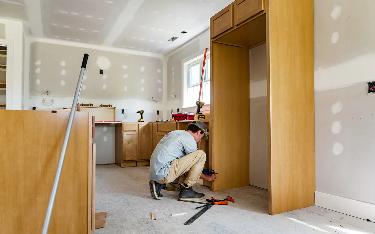
On a wall that is still open, this is a five-minute problem that costs the price of an offcut. A piece of 18 mm (3/4 in) plywood let in between the studs at the height the bracket will sit, or a horizontal noggin of the same stuff as the frame, screwed through the studs into its ends, turns a bay into a fixing surface. Make it taller than you think you need — 300 mm covers every bracket height anyone will subsequently choose — and take it across two bays where the wall is destined for a television, because nobody centres a screen where the drawing said they would.
Retrofit is the same idea at ten times the effort. Cut the board out between two stud centres so both edges of the opening land on timber, let the pattress in, screw the piece back and accept that you have created an unbacked butt joint in the middle of a wall. That joint is the visible cost of the whole exercise: butt joints have no taper to bury the tape in, and a rushed one telegraphs under any raking light for the life of the decoration. Board application and jointing are covered by ASTM C840 and Gypsum Association GA-216 in North America and by BS 8212 in the UK, and their advice on fastener depth is the part people ignore — a screw head that has broken the paper has stopped holding the board.
Materials matter more than people expect, because the moment you are re-boarding you are also buying screws and tape, and the pattress is the cheapest line on the sheet. On a refurbishment where the whole room is being lined anyway, building in blocking at every future fixing point — television, wall units, rails, a heavy mirror, a basin — adds an offcut per bay and nothing else. That is a genuinely free decision made once, against a retrofit that involves dust sheets, a plasterer and a decorator.
Fixing into the pattress afterwards is a timber withdrawal problem, not a plasterboard one. The screw has to pass through the full board thickness and still get proper thread engagement in the ply, which usually means it is longer than whatever came in the bracket's box. Coach screws into a ply pattress are a reasonable answer for a heavy mount; screws into the end grain of anything are not. Before cutting, confirm what is in the bay — socket drops below, switch drops above, and pipework anywhere at all — and remember that a stud you decide to drill through is governed by the boring and notching limits in the IRC's wall framing provisions, not by what fits.
- Confirm what is in the bay before a blade goes in: socket and switch drops, and any pipework crossing it.
- Mark the cut on the centre lines of the studs either side, so both edges of the opening land on timber.
- Cut the board back to those lines and keep the piece, because it is also the patch.
- Fix the noggin or ply pattress between the studs at bracket height, screwed through the studs into its ends.
- Photograph it against a tape held on the floor, so the height can be found again through a finished wall.
- Screw the patch back to the studs and to the pattress, heads set just below the paper and no deeper.
- Tape and fill it as the unbacked butt joint it is, and give it the extra width that a butt joint needs.
Where the room is being lined anyway, the board, screw and tape quantities are the real cost of the wall — and the blocking that makes every future fixing trivial does not move any of these three numbers.
SettingsSettings for this calculation
The standard allowance most suppliers and estimating guides assume for ordinary work.
The length of the room, wall to wall.
The width of the room, wall to wall.
Floor-to-ceiling height.
Door openings don't need drywall.
Window openings don't need drywall.
What each door opening takes off the boarded area. The default suits a standard interior door with its frame.
What each window opening takes off the boarded area. The default suits a typical window.
Extra material for cuts, mistakes, and irregular walls.
Estimated drywall needed
12 sheets (4x8 ft)
- Gross wall area
- 392 ft²
- Doors + windows area (subtracted)
- 51.13 ft²
- Net wall area
- 340.87 ft²
- Area with waste factor
- 374.96 ft²
- Joint tape needed
- 126.12 linear ft
- Drywall screws needed
- 384 screws
They open the calculator with your figures already in it
Drywall Calculator: 12 sheets (4x8 ft) — shown in imperial, US market. The link sets both, so the result they see is the one on your screen.
Estimated cost — your price
This site holds no price list for this material — local prices vary too much to publish honestly. Enter your supplier's price and the result is costed with it.
Schematic layout — positions are illustrative, quantities are exact. This calculator is told how many doors and windows there are, never where they sit or how big each one is, so they are drawn evenly spaced at the standard allowance it deducts. Moving one would change nothing in the numbers above.
What this calculation does not cover
- One area stands for every door and one for every window, so a room with a sliding patio door and a small landing window takes the same off the boarding for each; enter the average of the openings a field stands for and the total taken off is exact, though no single wall's share is.
- That deduction is taken before the waste factor is applied, so the board cut out of a doorway or a window head is treated as material recovered elsewhere on the job, and the reveals returning into each opening are subtracted here rather than added even though they still have to be boarded and finished.
- Wall area is 2 × (length + width) × height — one closed rectangle at a single height — so a chimney breast, an alcove, a stub partition or a closet wall standing inside the room adds boarded surface the perimeter never sees, and a sloped or vaulted ceiling cannot be entered at all.
- The sheet figure is an area division, waste-loaded area over one board's area (2.973 m² for a 4x8 ft sheet, 2.88 m² for a 2400x1200 mm one) rounded up once at the end, which assumes one board size, one layer, and offcuts used down to the last piece rather than a hanging plan; 12 ft boards, short 1800x900 boards or a double-layer partition all give a different count.
- Screws are simply 32 per sheet, the figure quoted for framing at 16 in centres, so the total does not move for 24 in or 600 mm centres, for metal furring or resilient bar, or for the tighter pattern a ceiling install takes — and since it multiplies the waste-loaded sheet count, whatever waste percentage you chose is carried into the screw number too.
- Joint tape is a flat 0.37 linear ft per square foot of net wall area, an average that knows nothing about your joint layout: boards hung vertically in a tall room, or a wall broken into short runs, generate more joint per square metre than that average assumes, and corner bead and the compound that fills the joints are outside this figure entirely.
Dot-and-dab, and the gap in the middle of the fixing
A dry-lined solid wall changes the problem entirely. The board is stuck to masonry on adhesive dabs and stands somewhere between 10 mm and 40 mm off the wall face, depending on how bad the wall was and how generous the fixer felt. Send a long screw and plug through into the masonry and the fixing crosses that void completely unsupported. Tightening then pulls the board towards the wall rather than clamping the bracket to anything: the sheet dishes, the bracket sits on a spring, and the connection is soft in exactly the direction the lever is loading it.
There are two correct answers and neither is a longer plug. The first is a purpose-made dry-lining fixing that carries a rigid steel sleeve through the void, so the tightening load lands on the masonry and the board is never compressed. The second is an accurately cut solid packer behind the bracket, sized to the measured gap at that specific point, which does the same thing with materials off the van. Either way the load path becomes continuous. Probe with a drill and a depth stop to find the real gap before ordering anything, since the void is rarely constant across a single bracket footprint.
What is behind the dabs then governs, and it is frequently not good masonry: soft handmade brick, lightweight aircrete block, or a wall previously chased for services and made good with whatever was on site. That is a different subject with its own rules on embedment, edge distance and hole cleaning, and it is covered properly in the concrete and masonry anchoring guide rather than approximated here. Scaling a plasterboard fixing's numbers into block is not a substitution — the substrate, the failure mode and the test behind the figure are all different things.
Steel studs take a screw differently
Non-structural steel partitions built to BS EN 14195 or ASTM C645 use sections in the region of 0.5 to 1.2 mm thick. A screw driven into a 0.6 mm flange engages barely more than one thread, and its withdrawal behaviour has nothing in common with the same screw in a 38 mm timber stud. Driving it harder does not help; it strips the hole and leaves the fixing turning freely. Screw types for this work are themselves standardised — ASTM C1002 for the thinner range, ASTM C954 for heavier gauges — and using the wrong one either snaps the screw or fails to pierce at all.
What does work is bearing rather than thread. A toggle passed through the flange and bearing on its back face uses the steel as a washer instead of as a nut. A length of channel or a proprietary backing section spanning three studs, fixed to each of them and then used as the bracket's substrate, spreads the load across the frame the way a wall unit rail does across timber. And in commercial fit-out, the honest answer is to nominate the load before the frame is built, because a heavier-gauge stud or a doubled section in the bracket's position costs almost nothing at framing stage and cannot be added once the boards are up.
The screw count for the boards themselves is a separate estimating question from the fixings that hold your bracket, and confusing the two is how a partition gets specified around the wrong constraint. Board fastening follows the system's own schedule; the bracket follows its own load path. They meet only in that both are trying to get to the same steel.
Proving it, then leaving a record
A finished fixing gives away nothing by eye, so load it before the television does. Hang a known weight — sandbags, a water container on a strop — from the bracket at the same standoff the real load will act at, and leave it there. Watch for movement against a straightedge laid across the plate or a laser line struck along the wall. How far above service load to go comes from the safety factor the fixing's manufacturer states, which is one more reason to know which kind of number the catalogue gave you. Movement that recovers when the load comes off is elastic and expected; movement that stays is the board crushing, and it does not stop.
Come back to it. Creep is the plasterboard failure mode nobody schedules a check for, and it is the one that actually catches people, because sustained load on a crushable core is a slow process with no warning noise. A fixing that has moved a millimetre in a week has told you what it intends to do over a year. Take it off the wall rather than adding a fifth toggle beside the four that are already losing.
Then write down what you found. The stud positions marked on a sketch, the pattress height photographed against a tape, the fixing type and the load it was proved at — that is ten minutes now against an afternoon of detector work for whoever next hangs something on that wall. And if the honest answer at any point in this process is that it will probably be fine, the alternatives are all cheap: a floor stand, a proprietary support frame that carries sanitaryware loads to the slab, or a bracket moved 150 mm to land on a stud. All three cost less than the wall repair, and considerably less than the screen.
What to establish while the bracket is still in its box
Work these out with a detector in one hand and the mount's own instructions in the other. Every one of them is cheaper to settle before a hole exists than after four of them do.
- Standoff and row spacing, measured off the bracket — The moment is load times standoff, resisted across the gap between fixing rows — both come from the plate and the screen, not from the packaging.
- A stud map drawn on the wall, verified point by point — Predict the count from the run and the centres first, then confirm each one; a detector agreeing with itself is not evidence.
- The fixing's published figure, and which figure it is — Mean failure, characteristic and recommended working loads can differ threefold, and no design code covers anchors in a gypsum lining.
- Board thickness and whether there are two layers — Grip length is part of every cavity fixing's approval, and a double layer puts most standard plugs outside the range they were tested in.
- Pattress material, if the answer is to open the wall — An 18 mm ply offcut across two bays, plus the board, screws and tape to close it again and the extra tape width a butt joint needs.
Opens the calculators above on one screen with the dimensions from this article already filled in. Quantities only — this site publishes no price list, because local prices vary too much to publish honestly.