
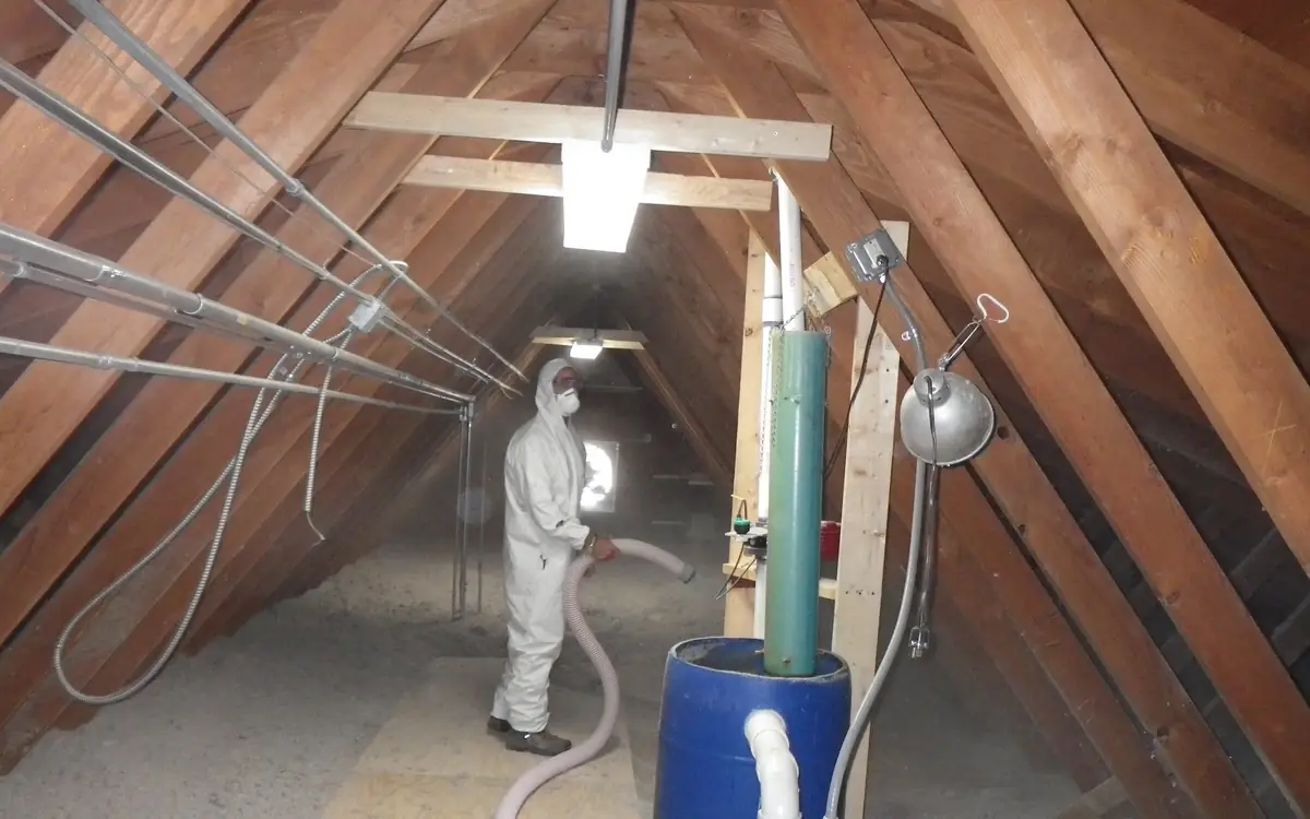
The void closes on Friday
Ventilation ductwork is the largest, least compressible service in a ceiling, and it arrives on site with the weakest claim on the space. Structure was there first. Drainage has gravity on its side and cannot be talked out of a fall. Cable trays can dogleg around anything. By the time the ventilation contractor unrolls a drawing, the easy runs are gone and the remaining route is the one nobody else wanted.
Losing that argument does not produce a redesign. It produces a squeeze: a flexible connector where a rigid sweep was drawn, a branch flattened to clear a beam, a manifold hung where nobody will ever reach it again, two extra bends to dodge a pipe that turned up late. Each of those is a permanent resistance, paid for by two fans running continuously for the life of the building, and every one of them disappears from view when the plasterboard goes on.
So the ventilation route is booked at first fix or it is not booked at all. Mark the unit position on the joists with its service envelope drawn around it. Set the two external sleeves through the wall with their falls cut. Drop the branch stubs into every room that will get a terminal, capped and labelled. Get the manifold locations agreed with whoever owns the void, in writing, while there is still a void to agree about. Photograph the whole run before the ceiling closes, branch by branch, with a tape in shot for scale. Six months on, when one bedroom will not hit its design flow, those photographs are the difference between a diagnosis and a hole cut in a finished ceiling.
The dwelling's number, then the rooms'
A heat recovery unit is sized against a continuous whole-dwelling rate, and that rate comes from the standard the jurisdiction has adopted. ASHRAE Standard 62.2 derives it from conditioned floor area together with a bedroom count standing in for occupancy; other regimes work from habitable room count or from a floor-area rate directly. What they share is the word continuous. The number is what the system delivers all day, not what it can reach when somebody presses boost.
That figure is the anchor for everything downstream. It fixes which unit in the range you can use, because a unit has to deliver it at the external static pressure your ducts impose and not at the free-blow figure on the front of the brochure. It fixes the branch sizes, because the room split is a division of this total. And it fixes the commissioning target, which is the only number anybody will check.
Read the fan curve, not the headline airflow. A unit advertised at a generous maximum may sit at a third of that once it is working against a real duct system, and the specific fan power quoted in the literature was measured at a pressure your installation is unlikely to reproduce. Choose so the design flow lands in the middle of the curve where the unit is quiet and has somewhere to go, not at the top where it has nothing left.
Confirm whether the adopted code counts the recovery unit as the whole ventilation strategy or as part of one. Some regimes still require intermittent extract capability in a wet room served by a continuous system, and finding that out at inspection is expensive.
Equipment selection, duct sizing and the room split all descend from one continuous figure for the whole dwelling, so settle that figure while the unit is still a line on a schedule.
The total conditioned floor area of the home.
ASHRAE 62.2 uses bedroom count as a proxy for expected occupancy.
Required continuous ventilation rate
78.3 CFM (continuous)
This is the standard ASHRAE 62.2 formula for continuous whole-house mechanical ventilation — actual equipment selection should also account for your specific ERV/HRV unit's rated efficiency and any local code amendments to the base ASHRAE formula.
- House area
- 1,610 sq ft
They open the calculator with your figures already in it
ERV/HRV Sizing Calculator: 78.3 CFM (continuous) — shown in imperial, US market. The link sets both, so the result they see is the one on your screen.
Add the equipment this sizes
This result is a specification — 78.3 CFM (continuous) — not a quantity. Put the thing it sizes into your project: how many, what you call it, and your supplier’s price.
What this calculation does not cover
- This is the whole-house rate only. ASHRAE 62.2 also requires local exhaust at kitchens and bathrooms, sized and ducted separately, and nothing here covers range hoods, bath fans or their duct runs.
- No infiltration credit and no envelope input. The figure is the total ventilation rate; current editions of the standard let a balanced system take credit for natural leakage, so the fan flow a leaky house actually needs can be lower than this. Nothing here reads a blower-door result or an air-tightness figure.
- This is a target flow, not an equipment selection. What a core actually delivers depends on external static pressure, duct length and fittings, filter loading, and how well supply and exhaust are balanced against each other, so a unit whose spec sheet lists this flow can fall well short once it is ducted. Commission with measured flows at the grilles.
- No climate adjustment. Defrost strategies that interrupt the supply side — recirculation, exhaust-only operation, or throttling the supply fan — cut the net fresh air delivered over a cold hour, while a preheater keeps outdoor air flowing continuously and pays for it in energy instead. The ERV-versus-HRV choice for humidity control is not modelled at all, and the number is the same in Miami and in Winnipeg.
- Bedroom count is the standard's occupancy proxy, not your occupancy or your pollutant load. A house run above the bedrooms-plus-one assumption, or one with an attached garage, unvented combustion or a workshop, needs more than this. Local codes and programs amend or replace the base ASHRAE rate, and this calculation does not check for that.
Which side of the core each room sits on
Every room in the dwelling sits on exactly one side of the heat exchanger, and the choice is made by what the room produces. Rooms that make moisture, grease or odour are on the extract side. Rooms where people sleep and sit are on the supply side. Circulation space is on neither: it is the transfer path that lets air move from one column to the other.
Those two columns have to sum to the same total, and they have to sum to the dwelling rate. That constraint is what turns the room split into arithmetic instead of preference. Add a second bathroom to the extract column and something on the supply side grows to match, or the unit runs unbalanced and the building starts moving air through its own fabric.
The transfer path is the part that gets built last and designed never. Air arriving in a bedroom has to leave it, which means a door undercut with a measured free area or a transfer grille through the wall, sized and not guessed. Carpet fitted after commissioning routinely halves an undercut, and a door that seals against a threshold strip converts a balanced system into a pressurised room with a whistle.
Boost is a separate conversation from the continuous rate. It exists for events — a shower, a cooking session, a laundry load — and it should be triggered by something the occupant cannot casually defeat: humidity, occupancy, an overrun timer wired to the light. A boost switch that only works when somebody remembers it is a boost rate that does not exist.
| Room | Side of the core | What sets the continuous rate | What boost is for |
|---|---|---|---|
| Bedroom | Supply | Occupancy, which the standard reads from bedroom count | Rarely boosted; night-time noise governs the terminal |
| Living or family room | Supply | The balance of the supply total once bedrooms are served | Open-plan cooking, where the kitchen extract cannot reach |
| Kitchen | Extract | The largest single continuous extract in most dwellings | Cooking, on a timer or a humidity signal |
| Bathroom or shower room | Extract | Moisture removal, set against the room and not the dwelling | Showering, with an overrun that runs on after the door opens |
| Utility or drying space | Extract | Laundry moisture, which arrives in bulk and without warning | Drying loads, often the largest humidity event of the week |
| WC | Extract | Odour, where moisture is not the driver | A short overrun on the light or occupancy switch |
| Hall, landing, stair | Neither | Nothing — it carries air between the two columns | Door undercuts and transfer grilles, sized as free area |
Where the box hangs, and what has to reach it
Put the unit inside the heated envelope. A recovery unit in a cold loft spends winter warming its own casing, condenses on surfaces the manufacturer never intended to be cold, and freezes its drain on the night it is needed most.
Where a loft position is genuinely unavoidable, the unit and every metre of duct around it get wrapped as though they were outside, because thermally they are.
The service envelope is bigger than the box. Filters come out annually at least, the core comes out for washing, and both come out forwards. A unit hung tight against a rafter with a water cylinder in front of it will be serviced once, by you, and never again. Leave the manufacturer's stated clearance on the access face and leave a way to reach it that does not involve a stepladder balanced on a joist.
Weight and vibration go together. Hang from structure, not from ceiling battens, on anti-vibration mounts if the manufacturer supplies them, and keep the casing off the plasterboard so it does not use the ceiling as a soundboard. A unit fixed to the party side of a bedroom wall will be audible in the bedroom no matter what the sound data says.
Height is a drainage decision as much as an access one. The condensate spigot needs fall from where it leaves the casing to wherever the water is going, and that fall has to exist over the whole route. Hanging the unit as high as the void allows costs nothing at the time and buys the drain the gradient it will need.
Duct type decided before duct route
Three families of duct show up on this work and they are not interchangeable. Rigid galvanised spiral is the lowest resistance per metre, holds its shape, cleans out and takes a proper sealed joint. Semi-rigid radial ducting runs continuously from a manifold to a terminal with no joints in the middle, which removes most of the leakage risk and most of the crawling. Flexible ducting is the cheapest and the worst, and its place is the final short connection where the manufacturer allows one.
Radial and branched are different systems, not different layouts. A radial system runs one unbroken duct per terminal from a supply and an extract manifold, which makes commissioning tractable because a valve setting affects that room and nothing else. A branched trunk-and-spur system uses less duct and gives you cross-talk between rooms sharing a spur, plus a balancing exercise where every adjustment moves every other reading.
Bend radius is where the design either survives contact with the void or does not. A tight bend in semi-rigid duct is a permanent restriction and there is no way to see it afterwards; the manufacturer publishes a minimum radius and it is not advice.
Two long sweeps will beat four short elbows over the same displacement every time, and a route that adds a metre of straight duct to delete a pair of bends is the shorter route in the only sense the fan measures.
Keep runs to a similar length within a manifold where the layout allows. Wildly unequal branches can still be balanced with valves, but you balance them by throttling the short ones down to match the long one, which means the fan works at the pressure the longest branch demands while most of the system throws the difference away.
Holding the run round and off the joists
A duct that has gone oval has already spent pressure. Flexible duct sags between supports into a series of low points that trap condensate and add resistance nobody costed. Semi-rigid duct laid across a loft and then buried under blown insulation gets crushed by the first person who kneels on it. Rigid spiral survives most of this and still needs support at the spacing its diameter and gauge require.
Support the duct, not the insulation. Hangers that bite through wrap compress it at every fixing, and a compressed section of a vapour-sealed cold duct is a cold spot with condensation waiting on it. Saddles that spread the load across the duct wall, sized to the outside diameter of the insulated assembly, keep both the shape and the thermal envelope intact.
Manifolds and plenum boxes need their own fixings. They are heavy, they carry the load of every branch hung off them, and they are exactly the component most often found resting on a ceiling joist with one screw through a flange. Fix them to structure and leave the branch spigots pointing where the ducts actually want to go, which is a decision made once and regretted for years.
Where the run crosses a joist, cut or drill within the limits the structural design allows and no further. A notch taken because the duct was 20 mm too low is a structural alteration performed by somebody with no authority to make it, and it will be found.
Support spacing is what keeps a run round, and a run that has gone oval has already spent pressure you will be short of at the far terminal — count the hangers off the measured route.
The total length of the straight duct run being supported.
The maximum allowed distance between hangers for this duct's size, gauge, and construction type.
Number of duct hangers needed
6 hangers
Maximum hanger spacing varies by duct size, gauge, and construction type per the SMACNA HVAC Duct Construction Standards table — confirm the correct maximum spacing for your specific duct before finalizing support layout.
- Bays along the duct run
- 5
- Hanger centres along the duct
- 8 ft
They open the calculator with your figures already in it
HVAC Duct Hanger Support Spacing Calculator: 6 hangers — shown in imperial, US market. The link sets both, so the result they see is the one on your screen.
Estimated cost — your price
This site holds no price list for this material — local prices vary too much to publish honestly. Enter your supplier's price and the result is costed with it.
What this calculation does not cover
- Spacing is one of the two numbers in a support, and the other one is missing here: what each hanger has to be made of. Strap and rod size, and the trapeze member under a large duct, come from the duct's half-perimeter and the load carried between supports — insulation, internal lining and any condensate sitting in a low spot all add to it. Hangers at exactly the right interval in undersized strap sag between them just the same.
- The connection at the top of the hanger is not in the count either, and that is where these actually fail. A screw into the flute of a metal deck, a wire looped over an open-web joist away from a panel point, or a pin driven into the underside of a slab each carry their own rated load, and the structure has to be willing to take a hanging load at that point at all.
- Fittings and anything heavy in the line need supports outside this spacing. Elbows and tees are commonly supported at each end rather than counted into the straight run, and fire dampers, in-line fans, coils and silencers are normally required to be carried independently so their weight never hangs off the duct seams. Where a seismic design category triggers it, transverse and longitudinal bracing is a separate system on its own spacing, and it is not what this counts.
The two ducts carrying outdoor air
Four ducts leave a recovery unit and two of them are at outdoor temperature. The intake duct runs from the external grille to the unit carrying whatever the weather is doing; the exhaust duct runs from the unit back out to its grille carrying air that the core has just stripped of heat and left cold and close to saturation. Both of those runs pass through a warm, humid building.
Untreated, they sweat. In winter the intake duct condenses room air on its outside along its whole length, and the drips land wherever the run happens to cross a ceiling. The exhaust duct does the same and is worse, because the air inside it is colder still. This is the single most common defect on otherwise competent installations, and the callback arrives as a ceiling stain nobody associates with ventilation.
The treatment is insulation with a genuinely continuous vapour barrier: taped at every joint, sealed where a hanger passes, and carried all the way to the terminal face at the wall. The last handspan is the one crews run short on and it is the coldest point on the run. Pre-insulated duct simplifies this and still needs its joints sealing. The two warm ducts — supply into the dwelling and extract out of it — are a different problem with a different answer. They carry conditioned air and their losses are energy, not water, so they get insulated where they pass outside the heated envelope and left alone where they do not.
Wrap is bought by area, and the area of the intake and exhaust runs includes every bend and the last handspan at the terminal face, which is precisely where crews run out.
SettingsSettings for this calculation
The standard allowance most suppliers and estimating guides assume for ordinary work.
The perimeter of the duct's cross-section (rectangular or round).
The total length of duct run to be wrapped.
Extra material to allow for overlaps, seams, and cutting around fittings.
Duct wrap material needed
290.4 ft²
They open the calculator with your figures already in it
Duct Insulation Wrap Area Calculator: 290 ft² — shown in imperial, US market. The link sets both, so the result they see is the one on your screen.
Estimated cost — your price
This site holds no price list for this material — local prices vary too much to publish honestly. Enter your supplier's price and the result is costed with it.
What this calculation does not cover
- Perimeter multiplied by length gives the duct's own outer surface, but the blanket has to pass around the outside of its own thickness, so the circumference it actually spans is larger than the perimeter entered. A rectangular duct gains roughly eight times the wrap thickness and a round duct gains 2π times it, so a run needs appreciably more blanket than its bare perimeter suggests — on a typical rectangular duct about a fifth more than the figure returned here at 10%. Enter the perimeter measured over the finished insulation if you want the ordering figure.
- The result is an area only, and says nothing about the wrap thickness or the installed R-value that area has to deliver. Duct wrap loses a substantial part of its out-of-the-roll R-value where it is compressed at corners and under the wire or straps holding it on, and the R-value required for duct in an attic, in an unconditioned space or buried is set by the energy code in force. Buying the right area of the wrong thickness still fails that check.
- The waste allowance is a flat percentage of the straight-run area, so it scales with length rather than with the number of fittings. Elbows, transitions, takeoffs and damper access panels are cut from rectangles larger than the surface they finish up covering, and hangers, trapeze supports and flanged joints interrupt the blanket, so a fitting-heavy run can outrun even the 20% this field allows.
- Only the blanket itself is quantified. Outward-clinch staples, FSK or foil tape over every longitudinal and circumferential seam and staple line, and mastic where the wrap meets a flange are all separate items, and on duct carrying cooled air it is the continuity of that vapour barrier, not the area of blanket, that decides whether moisture condenses inside the insulation.
- This is an external wrap take-off and does not estimate the alternatives. Internal acoustic liner is measured on the duct's inside faces and also cuts the free cross-section the duct delivers; rigid board and duct board are ordered as boards on a mechanical fastener grid rather than as a continuous roll.
Terminals, throw, and the bed underneath
A supply terminal is a directional device. Air leaves an adjustable cone valve or a linear diffuser as a jet, attaches itself to the ceiling if it is close enough to it, and travels across the room losing velocity as it entrains the air around it. Get that throw right and the room mixes with no draught anywhere. Get it wrong and a cold jet drops out of the ceiling directly onto whoever is sitting under it.
Position accordingly. Keep supply valves away from the head of a bed and away from a desk chair, and let the throw run the length of the room instead of across its width. Extract valves go high in wet rooms where the moisture is, and away from the door, so the room's air crosses the space on the way out instead of short-circuiting from the undercut straight up the duct.
Valves have to stay adjustable to be commissioned. A cone valve painted into a ceiling is a fixed orifice at whatever setting the decorator left it; a valve fitted with its locknut already seized is the same. Fit them after painting or fit them with a protective cap, and check every one turns before the commissioning day starts.
Free area matters as much on the terminal as it does on the external grille. A decorative plate chosen by the customer can have a fraction of the free area of the valve it replaced, and the reading at that room drops without anything else in the system changing.
Sound arrives down the same duct as the air
Two fans running continuously make noise that goes somewhere. Some of it radiates off the casing into whatever space the unit sits in. Most of it travels down the ducts as airborne sound and comes out of a terminal in a bedroom at three in the morning, which is when the occupant switches the system off and stops ventilating the house.
The standard answers are attenuators in the supply and extract ducts close to the unit, generous duct sizes so air velocity at the terminal stays low, and long flexible runs of semi-rigid duct that absorb some of what passes through them. Sizing a system for a velocity a category quieter than the maximum is the cheapest acoustic measure available, and it also buys back pressure.
Cross-talk is the second sound problem and it is a design fault, not an installation one. On a branched system, two rooms on one spur are acoustically connected through the duct: a conversation in one is audible in the other. A radial layout removes the path entirely, and where a branched layout is fixed, a branch attenuator on each of the two rooms is the retrofit.
Regenerated noise happens after all of that. A tight bend, a partly closed valve or a crushed section produces turbulence, and turbulence downstream of an attenuator is noise the attenuator cannot touch. Anything you throttle hard during commissioning is a candidate to be heard.
Attenuators are specified by the loss they add at each octave band, and two in series do not simply add up — check what the pair actually buys the bedroom branch.
The manufacturer-rated insertion loss for the first silencer or lined duct section in the path.
The manufacturer-rated insertion loss for the second silencer or lined duct section in the path.
The manufacturer-rated insertion loss for a third silencer or lined duct section, if present.
Estimated total insertion loss
25 dB
This is a simplified additive estimate for first-pass screening only — it does not account for regenerated (self) noise from the silencers/airflow, cross-talk, or flanking paths, and combines losses without full octave-band detail. A complete noise control analysis for a critical space (e.g. a recording studio, courtroom, or hospital) requires a qualified acoustics engineer's multi-octave-band evaluation.
They open the calculator with your figures already in it
HVAC Duct Silencer Cumulative Insertion Loss Calculator: 25 dB — shown in imperial, US market. The link sets both, so the result they see is the one on your screen.
Add the equipment this sizes
This result is a specification — 25 dB — not a quantity. Put the thing it sizes into your project: how many, what you call it, and your supplier’s price.
What this calculation does not cover
- Every silencer in that stack costs static pressure. A packed unit at design velocity typically adds 25 to 125 Pa (a tenth to half an inch w.g.), and three in series can push the fan to a larger wheel or a higher speed — which puts more sound power into the duct at the same time, so attenuation bolted on late in a design partly eats itself. The pressure drop is printed on the same manufacturer's table as the insertion loss, and this total does not touch it.
- Attenuation is not a sound level. Knowing the path removes 25 dB says nothing about where the room ends up: that comes from the fan's sound power, everything else along the path, and the room's own size and absorption — and it is the resulting NC or dBA in the occupied space that a specification is written against. A loud enough source can be 25 dB quieter and still too loud for the room it discharges into.
The two holes in the outside wall
The external terminals decide the quality of the air the system distributes, and they get sited late, by whoever is holding the core drill. Intake and exhaust have to be far enough apart that the unit does not breathe its own exhaust; the manufacturer publishes a separation and the prevailing wind decides whether that separation is generous or optimistic. Put the intake on the side the wind arrives from where you can.
Keep the intake away from everything that produces what you do not want indoors: flue terminals, plumbing vents, dryer ducts, bin stores, parking spaces, the ground itself. Height above finished ground level matters for splash, for snow and for road dust, and height above a flat roof matters for the same reasons plus standing water.
Grilles are chosen by free area, not by outside dimension. A weather louvre with an insect mesh can have well under half the free area of the duct behind it, and the mesh is the part that blocks. Choose a grille whose free area suits the design flow, then make the mesh accessible so it can be cleaned, because it will need it.
Sleeve both penetrations with a fall to the outside, seal the sleeve to the air barrier and the weather barrier on their own terms, and carry the duct insulation right through to the grille. A sleeve cut level is a rain path; a sleeve sealed only on the inside face is a wall cavity that fills up quietly.
The water the core makes, and the ice behind it
On the extract side of the exchanger, warm humid air from kitchens and bathrooms is cooled below its dew point and gives up its water inside the unit. That is the machine working correctly. The condensate has to be taken away with a fall the whole distance, through a trap deep enough to hold a seal against the fan pressure trying to pull it apart, and into a drain that has an air gap and will not backfeed sewer gas into the ceiling.
Trap depth is a pressure calculation the manufacturer has already performed; use their fitting or their dimension. A shallow trap on a unit running at full fan speed blows dry, and once it is dry the drain becomes an open connection between the ductwork and the drainage system. In summer, a system producing no condensate lets a trap evaporate dry with the same result, which is why dry-trap seal devices exist.
Freezing is the other half of the story. A drain run in a cold void freezes, backs the condensate up into the unit, and floods it onto the ceiling below. Keep the drain inside the warm envelope, insulate it where you cannot, and give it fall throughout, with no horizontal runs where water can stand.
Frost protection at the core is a separate mechanism and the manufacturer's choice governs. A preheater on the intake keeps the incoming air above the temperature at which the exhaust side would ice, and pays for it in electricity. Recirculation defrost closes the intake and warms the core with indoor air. Unbalanced defrost simply reduces or stops the supply fan while extract continues, which clears the ice and, for the duration, depressurises the dwelling.
Whichever strategy the unit uses, it costs recovered heat, and how much depends on how effective the core is and how cold the design condition gets. In a mild maritime climate the frost cycle is an occasional nuisance. In a continental winter it runs often enough to be a design input, and it interacts with any combustion appliance in the building — an unbalanced defrost on a house with an open flue is worth checking rather than assuming.
Defrost strategy is an argument about how much recovered heat you are willing to hand back, so put the core's rated effectiveness against your design temperature difference and see what is at stake.
The ERV/HRV's rated or design supply airflow.
The temperature difference between the outdoor and indoor (or exhaust) airstreams entering the unit.
The fraction of the available sensible energy difference the unit actually transfers between airstreams.
Recovered sensible energy
15,100 BTU/hr
Use the specific ERV/HRV unit's AHRI 1060-certified Sensible Recovery Effectiveness rating at conditions close to your design case — SRE varies with airflow and temperature/humidity conditions, so a single manufacturer-published number applied outside its rated conditions is an approximation.
They open the calculator with your figures already in it
ERV/HRV Sensible Energy Recovery Calculator: 15,118 BTU/hr — shown in imperial, US market. The link sets both, so the result they see is the one on your screen.
Add the equipment this sizes
This result is a specification — 15,100 BTU/hr — not a quantity. Put the thing it sizes into your project: how many, what you call it, and your supplier’s price.
What this calculation does not cover
- Sensible heat only, which on an ERV is half the story. Moisture moved across the core is counted by a separate latent effectiveness, and in a humid climate that latent recovery can carry as much energy as this figure does — comparing an ERV against an HRV on this number alone hides the very thing that separates them.
- This is gross recovery at one instant, not what the unit saves. Both fans run continuously against the core's pressure drop and that parasitic power comes straight off the benefit, while in cold weather the defrost cycle interrupts recovery for a share of exactly the hours it is wanted. A payback worked from this figure is optimistic on both counts.
- Assumes supply and exhaust flows are equal, because that is the condition the effectiveness was certified at. Unequal duct runs, a loaded filter or an exhaust-dominant house shift the flows apart, so the unit recovers something other than its rating and pushes the imbalance into air moving through the building fabric instead.
Proving it, valve by valve
A ventilation system is not commissioned by being switched on. It is commissioned by measuring the flow at every terminal, adjusting until each one sits inside tolerance, and writing the results down. Everything before this point was preparation for a set of readings, and the readings are what the client, the inspector and the next contractor will look at.
Instrument choice decides whether the numbers mean anything. A powered flow hood compensates for the resistance the hood itself adds and is the right tool at a valve. A vane anemometer traversed across a terminal needs the correct k-factor for that specific valve at that specific setting, and manufacturers publish those factors for exactly this reason. A reading taken with the wrong factor is a confident number that is simply wrong.
Commissioning is iterative because the terminals are hydraulically connected. Close down the terminal that is over-delivering and every other reading on that manifold rises. Expect two or three full passes on a radial system and more on a branched one, and expect the last pass to move things by a few percent that the first pass moved by half.
Finish by reconciling the totals. The sum of the supply readings and the sum of the extract readings should match each other and match the dwelling rate the design started from. If they do not, the fault is upstream of the valves — leakage, a crushed duct, a blocked external mesh — and no amount of further valve adjustment will fix it.
- Fit the filters the system will actually run with, and confirm every valve is at its factory-open position.
- Run the unit at its commissioning speed and let the readings settle before recording anything.
- Measure each terminal in turn, writing the value against the room name and not against a valve number on a drawing.
- Adjust the terminal furthest from its design flow first, then re-measure the whole side, because every adjustment moves every other reading.
- Repeat passes until each terminal sits within the tolerance the specification allows.
- Set the fan speeds so both column totals match the dwelling rate, then verify the boost rate at the wet rooms.
- Lock every valve, record the settings and the measured flows, and leave a copy at the unit as well as in the handover file.
Commissioning is a percentage question and not a pass or fail one — each terminal reading has to be expressed against its design flow to know which valve to touch next.
The zone's specified design airflow from the mechanical drawings.
The zone's actual field-measured airflow.
Airflow balance deviation
-8 %
Within the commonly-specified ±10% TAB tolerance.
They open the calculator with your figures already in it
HVAC Zone Airflow Balancing Percent Calculator: -8 % — shown in imperial, US market. The link sets both, so the result they see is the one on your screen.
What this calculation does not cover
- The deviation is only as trustworthy as the reading behind it. A balancing hood is accurate to a few percent at best, and considerably worse when it is not matched to the diffuser, is held off square, or back-pressures a low-flow outlet enough to depress the very flow it is measuring. So a zone showing a small deviation may be a hood problem rather than a damper problem — confirm a marginal reading by a second method before anything gets adjusted.
- Zones are not independent, so any one zone's percentage is a moving target. Closing a damper on one branch pushes that air into every other outlet on the same trunk, which means a zone set exactly to design early in the pass has moved by the time the last zone is set. Balancing is proportional and iterative across the whole system, and a per-zone figure only means something on a final pass with everything else settled in position.
- Sitting inside the tolerance is not the same as delivering what the zone needs. Where the design airflow was set by ventilation rather than by heating or cooling load, a reading 9 % under design passes this arithmetic while the space receives 9 % less outdoor air than it is required to. And a system whose zones all sit on the low side of tolerance sums to a supply total well short of the fan's design flow with every individual number still reading acceptable.
What the second winter shows
Recovery ventilation degrades quietly and on a predictable schedule. Filters load and airflow falls, which the occupant experiences as a house that feels stuffier without anything having broken. External meshes clog with pollen and dust. Kitchen extract valves accumulate a film that changes their free area. None of this triggers an alarm, and by the second winter a system commissioned perfectly can be delivering a fraction of its design flow.
That is why the access decisions made at first fix matter more than any other. If filters can be changed from a landing in two minutes with no tools, they will be. If the change involves a loft hatch, a plank and a torch, the system will run on the original set until something else forces the issue.
Hand over more than a remote control. The occupant needs to know what the boost does, why the unit runs continuously, what a filter change looks like, and — most importantly — why switching it off in winter to save money produces condensation on the windows within a fortnight. A one-page sheet at the unit outlasts every verbal explanation. Leave the commissioning record where the next person will find it: valve settings, measured flows, fan speeds, filter sizes, and the date. A future imbalance is trivially diagnosed against a record of what the system did on the day it worked, and nearly impossible to diagnose without one.
Ordering off the reflected ceiling plan
Ventilation quantities come off the route, not the schedule. Measure the runs you can actually build in the void you were given, then order for that route.
- Whole-dwelling continuous rate, then the room split — Both columns sum to the same total; adding a wet room grows the supply side to match.
- Duct by family, with flexible restricted to final connections — Rigid or semi-rigid for the run; count bends as well as metres, since the radius limit governs the route.
- Insulation and vapour tape for the intake and exhaust runs — Measured to the terminal face, including bends — the last handspan at the wall is the coldest point.
- Hangers, saddles and manifold fixings — Sized to the outside diameter of the insulated assembly so the wrap is not compressed at every support.
- Terminals, valves and external grilles — Counted per room, with free area checked against the design flow, not against the duct diameter.
- Condensate trap, fall and a drain point that exists — Trap depth per the manufacturer against fan pressure; the route stays inside the heated envelope.
- Attenuators for the bedroom branches — Specified by octave-band insertion loss, positioned close to the unit and again on any shared spur.
Opens the calculators above on one screen with the dimensions from this article already filled in. Quantities only — this site publishes no price list, because local prices vary too much to publish honestly.