
SettingsSettings for this calculationUS
The total floor area to be heated.
Measure the usable floor area of the room(s) on this loop, excluding cabinetry footprints and fixed fixtures if they won't have tubing under them.
Tighter spacing delivers more heat per square foot but uses more tubing.
6 in spacing is common near exterior walls and cold floors (e.g. over a garage); 12 in is often enough for interior rooms with less heat loss.
Tubing for the bends, wall penetrations and loop ends where each circuit starts and finishes.
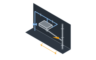
Every loop turns at each wall, rises to the manifold and returns, and those turns and tails are tubing the floor area does not account for. A room beside its manifold manages on ten; leader runs to a manifold elsewhere are not in this figure at any setting — enter them as the leader length below.
The tubing between the heated area and a manifold outside it, flow and return together. Leave at 0 when the manifold is in the room.
Every circuit runs its own flow and its own return to the manifold, so the leaders come to circuits × 2 × the route: three circuits on a 4 m (13 ft) route are 24 m (79 ft) of tube. It is a measured length, so it is added to the total as it stands; the connection allowance is not applied to it. Leaders also count toward each circuit's maximum loop length.
PEX tubing needed
323 linear ft of PEX
This estimates tubing length only. Actual loop layout, maximum loop length per manifold circuit, and manifold port count should be confirmed against your specific radiant system's design guidelines.
- Tubing before manifold allowance
- 293.33 linear ft
They open the calculator with your figures already in it
Radiant Floor PEX Tubing Calculator: 323 linear ft of PEX — shown in imperial, US market. The link sets both, so the result they see is the one on your screen.
Show calculation logicHide calculation logic
How this was calculated
Formula source(s)
- Standard radiant-floor industry formula: tubing length (ft) = floor area (sq ft) x (12 / tube spacing in inches)
- 10% extra is standard to account for manifold connections, wall penetrations, and the return run at each loop's start and end
- Leader tubing (the flow and return between the heated area and a manifold outside it) is a measured length: circuits x 2 x the route, added to the total as it stands
Inputs used
- Floor Area
- 220 sq ft
- Tube Spacing
- 9 in — standard
- Connection Allowance (%)
- 10
- Leader Length (Flow and Return)
- 0 ft
Intermediate steps
- Tubing before manifold allowance
- 293.33 linear ft
Confidence note: This estimates tubing length only. Actual loop layout, maximum loop length per manifold circuit, and manifold port count should be confirmed against your specific radiant system's design guidelines.
What this calculation does not cover
- This is a tubing-length estimate, not a heating design. It takes your spacing as a given and never checks that the spacing, supply water temperature and floor covering can actually meet the room's heat loss — that comes from a room-by-room heat-loss calculation and the tubing manufacturer's floor-output tables.
- The answer is one total length, not a loop layout. It does not divide the area into circuits of roughly equal length, apply any maximum loop length, or tell you how many manifold ports you need. Any area beyond a small room needs several loops off a manifold rather than one continuous run.
- Tubing diameter is not an input, so nothing in the result reflects pressure drop, flow rate or circulator head. The same total length behaves very differently in 3/8 in (9.5 mm) tube than in 5/8 in (16 mm), and diameter is what sets the practical loop-length limit.
- The connection allowance covers bends and connections in and around the heated area only. Leader runs from a manifold sitting outside the room are not in it at any setting — they are counted only when you enter them as the leader length, which is added to the total as measured, with no allowance on top.
- One spacing is applied uniformly to the whole area you enter. Mixed-spacing zones, tighter perimeter loops at exterior walls, voids under cabinets and fixtures, and setbacks from walls, expansion joints and floor penetrations all have to be handled by adjusting the area or running the calculation per zone. Staples, rails, clips, slab insulation and the manifold itself are not counted.
Estimated cost — your price
This site holds no price list for this material — local prices vary too much to publish honestly. Enter your supplier's price and the result is costed with it.
Part of bigger jobs
This trade is one line of several job takeoffs. Run the whole job and every other trade comes back with it, off the same measurements.
Or plan the space itself: measure it once, doors and windows included, and this figure comes back worked out on that space, with what goes with it.
also measuresFloor Crack Isolation Membrane CoverageFloor & Wall TileThinset & Tile Adhesive
also measuresFoam Board InsulationPipe Insulation
also measuresMasking and Protection MaterialsFoam Board InsulationSelf-Leveling Underlayment (SLU) VolumeFloor & Wall TileThinset & Tile AdhesiveFloor Transition StripSkip & Dumpster Size
Computed in your browser — nothing you enter is uploaded. Presented in US customary units and US trade terminology. Where a formula follows a published standard, that standard and its edition are cited beside it on this page; where none governs, the page says so. Local amendments override model codes — verify against the code in force where you build.
Sources checked 2026-09-26 · v1.2.0
Regulatory standards & verification citations3
- Standard radiant-floor industry formula: tubing length (ft) = floor area (sq ft) x (12 / tube spacing in inches)
- 10% extra is standard to account for manifold connections, wall penetrations, and the return run at each loop's start and end
- Leader tubing (the flow and return between the heated area and a manifold outside it) is a measured length: circuits x 2 x the route, added to the total as it stands
Cite this page
Your workspace
Most jobs need more than one number. Add the calculators you need next and they open right here, underneath this one — your figures stay on screen and nothing is lost to a page change.
Tools and safety for this job
To lay the underfloor heating pipe loops. Generic types, no brands, no prices.
Protection this work requires
- Boards, blocks and bagged material cause most lasting back injuries on small sites: two people or a lifter for full sheets, and never a bag on one shoulder up a ladder.
- Knives cause more site injuries than any power tool: cut away from your body, change blades often, and wear cut-resistant gloves to EN 388 level C for repeated cutting.
- Loose sheeting, trailing leads and offcuts turn every trip across a room into a fall: tape protection down at every edge, run leads along the walls, and keep the way in clear of waste.
Lay the underfloor heating pipe loops: Laying and clipping pipe to a drawn layout is within reach of a competent installer. The loop layout, the spacing, how long each loop may be and the flow temperature it runs at are the heating designer's; this site never sizes the loops, and its radiant floor page measures the pipe for a spacing it is given. The loops are pressure-tested before anything covers them and kept under pressure while a screed goes down, which is the pressure test's own row.
Show the 5 tools this job needsHide tools
Essential
Plastic pipe shears
Tape measure
Recommended
Chalk line
Staple gun
Utility knife
Also needed as materials: chalk refill, replacement blades, staples.
what each hvac tool is for, and the spec that decides which to buy where one does.