
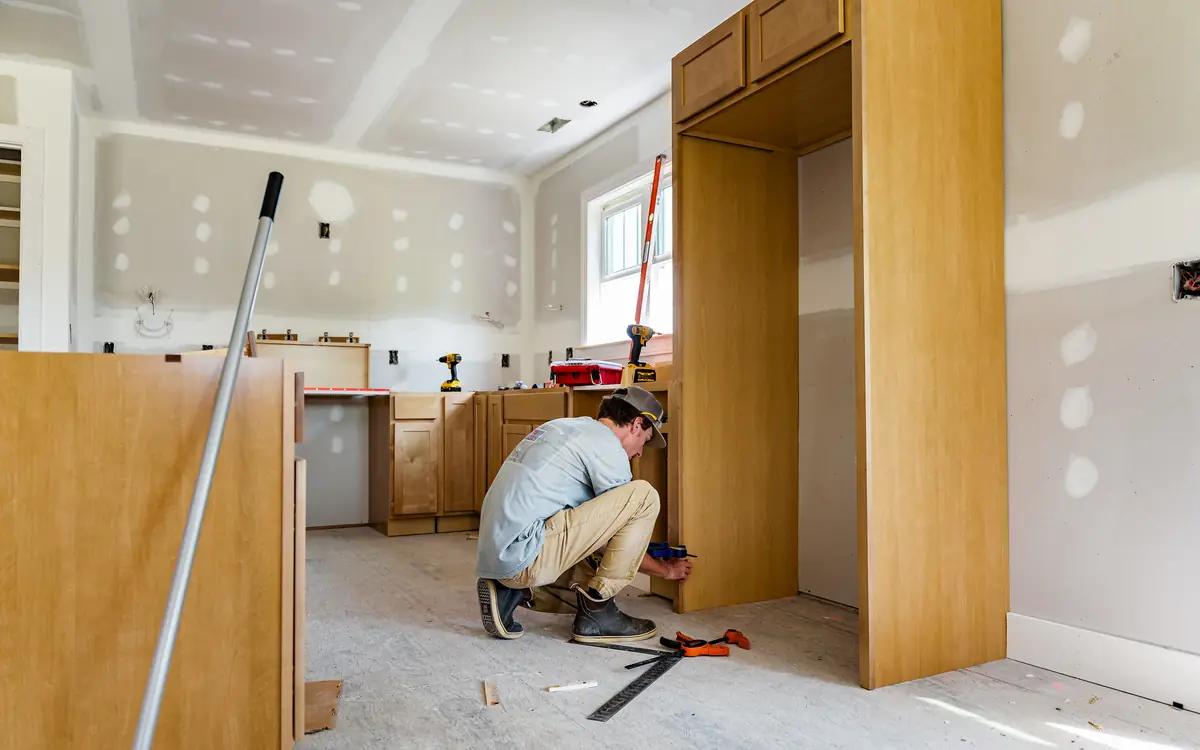
A Hundred and Eighty Millimetres of Spare Worktop
Put the tape on the 3 m length before the jig comes out of the van and work out what will be left once both legs are cut. On the job this article is written around — a 1.9 m run under the window meeting a 1.5 m run at an internal corner, 600 mm postformed tops on standard base units — the answer is about 180 mm. That offcut is not waste. It is the only piece of this worktop you are allowed to ruin, it is the same board and the same laminate as the corner you are about to cut for real, and the moment it goes in the skip the job has no rehearsal in it.
Almost everything else here is recoverable. A scribe cut two millimetres shy can be taken back. An upstand cut short is an upstand. Even a badly placed sink cutout announces itself while the pencil is still in your hand. The corner joint is the exception, because the two halves are mirror images of one another and there is no operation that converts a female cut into a male one. Get the profile on the wrong end, or the wrong face up, and you are holding a piece that is short by the depth of the corner — on a 600 mm top, 600 mm you have not got and the merchant shut at twelve.
Where the Three Metres Goes
Measure the two walls, not the units, and take each one at the height the worktop will sit rather than at the floor. Suppose they come back at 1,900 mm and 1,500 mm to the corner. That is 3,400 mm of finished run and it is emphatically not 3,400 mm of worktop, because at an internal corner one top runs through and the other stops against it. The through piece is cut to its full 1,900 mm. The abutting piece only has to cross the remaining 900 mm, because the first 600 mm out from the corner wall is already covered by the top it butts into.
So the material is 1,900 plus 900, and to that you add the crosscut kerf and the width of the router pass that separates the two — call the pair of them 20 mm, and the arithmetic lands at 2,820 mm out of a 3,000 mm board. Every internal corner in a run does the same thing: it gives you one worktop depth back. On a U-shaped kitchen with two corners that is 1.2 m of top nobody buys, and a takeoff built by adding wall lengths together will order a stick more than the job needs.
Decide where the joint lands before deciding anything else about it. It wants a cabinet gable directly beneath it so both halves are carried, which in practice means the joint line sits over an end panel or a shared side rather than over the void above an integrated dishwasher or a slide-in cooker. Keep it out of the sink and hob cutouts entirely — makers state a minimum distance from any cutout to a joint and to the front edge, and the strip of core left between two openings is the thinnest structural part of the whole top. If the layout gives you a choice, put the joint on the dry side of the room rather than the drainer side.
Then cut in the order that keeps the recoverable operations last. The joint first, while both pieces are still full length and there is board to spare either side of the profile; then dry-assemble the corner on the units and mark the free ends against the walls; then the scribes; then the cutouts, with the tops in place and the joint already proved. Cutting to length first feels tidy and removes the margin you need when the jig walks 3 mm on the second pass.
| Piece | Wall measurement | Cut length | Why it is not the wall figure |
|---|---|---|---|
| Through piece, window wall | 1,900 mm | 1,900 mm plus scribe allowance | Runs past the corner, so it is cut to the wall it finishes against |
| Abutting piece, side wall | 1,500 mm | 900 mm plus the male tongue | Loses one worktop depth to the piece standing in its way |
| Kerf and cutter waste | — | About 20 mm | One crosscut plus the material the router pass removes between them |
| Left on the board | — | About 180 mm | The practice joint, and an end cap offcut if a free end needs one |
Enter the finished run — both legs measured wall to wall, 3.4 m on the job above — and set the depth to the top you are actually fitting rather than leaving the 25.5 in default in place. The backsplash half of the answer is right at that figure, because a splash does run the full 3.4 m of wall. The countertop half is not: length times depth counts the 600 mm corner square twice over, so put the run in as 2.8 m instead when what you want is the surface there is to seal and maintain. That same worktop depth per internal corner is also what separates the wall measurements from the sticks you order, because the through piece has already covered that ground.
The total length of counter along the wall(s), including corners.
Standard kitchen counter depth is about 25-26 in (64-66 cm).
4 in (10 cm) is a standard minimal splash; set higher for a full backsplash to the cabinets, or 0 for none.
Estimated countertop area needed
31.96 sq ft (total)
- Countertop surface
- 27.63 sq ft
- Backsplash
- 4.33 sq ft
They open the calculator with your figures already in it
Countertop Area Calculator: 31.96 sq ft (total) — shown in imperial, US market. The link sets both, so the result they see is the one on your screen.
Estimated cost — your price
This site holds no price list for this material — local prices vary too much to publish honestly. Enter your supplier's price and the result is costed with it.
What this calculation does not cover
- This is GROSS area, with nothing deducted for the sink, the hob, tap holes or drainer grooves — which is how a fabricator quotes at the enquiry stage, because the slab has to be bought whole and the cut-outs are labour rather than savings.
- It is not a template. Stone and engineered stone are cut to a template taken in the finished room once the base units are in and levelled, and that measurement, not this one, is what gets cut.
- Seams, edge profiles and the extra material a book-matched or heavily veined slab needs are priced separately and can move the slab count without moving this area.
What Is Under the Pattern
The decorative face is high-pressure decorative laminate, well under a millimetre thick, specified in Britain and Europe by BS EN 438 High-pressure decorative laminates (HPL) — Sheets based on thermosetting resins, and in North America by ANSI/NEMA LD 3. It is hard, it is dimensionally stable and it is genuinely waterproof. It is also only on the top surface and wrapped around the postformed front roll. Everywhere else — both ends, the back edge, the underside of the roll, every hole you drill and every line you cut — is core.
The core is particleboard, and which particleboard matters more than anything else on the delivery note. BS EN 312 Particleboards — Specifications separates board types by service condition: P2 is for interior fitments in dry conditions, P3 is the non-load-bearing board rated for humid conditions, and the maker declares which one is under the laminate. The behaviour that separates them is measured by BS EN 317 Particleboards and fibreboards — Determination of swelling in thickness after immersion in water, and the important thing about that test is what it measures. Not strength loss. Thickness gain. The board gets bigger.
It also stays bigger. Swelling in a resin-bonded chipboard is the springback of compressed chips released when the bond between them fails, and nothing brings them back down. That is the whole of the six-month failure this article exists to prevent: a ridge you can feel with a fingertip along a joint line or around a sink cutout, permanent from the day it appears, and repairable only by replacing the top. The laminate above it is undamaged and irrelevant, because the water never went through the laminate. It went in at a cut edge somebody did not seal.
A worktop cut through on the joint line
- Upstand and its bead — closes the gap between the scribed back edge and a wall that is neither plumb nor straight, and takes a flexible sealant rather than a rigid fill Countertop Area Calculator
- Sealant at the wall junction — the line that stops splash reaching the raw back edge, which on a scribed top is freshly cut core rather than factory edge Caulk & Sealant Calculator
- Decorative laminate face — the only waterproof surface on the whole top, present on the upper face and round the postformed roll and nowhere else
- Particleboard core — the layer that swells and never recovers, declared as a board type under BS EN 312 and exposed at every cut you make
- Balancing laminate — the backing sheet on the underside, there to match the moisture take-up of the face so the board does not cup toward the dry side
- Connector bolts in their pockets — three of them across the depth, drawing the two mating faces together from the front roll back to the wall
- Cabinet rails — what the top is screwed down to from below, and what gets packed when the two halves of a joint are not flush
Male, Female, and the Mirror-Image Corner
Both pieces get routed. The jig makes two complementary profiles — one with a tongue standing proud, one with the matching recess — and neither piece arrives at the corner untouched. The profile itself is the butt-and-scribe, usually called a mason's mitre, and it reads on the finished top as a short 45 degree section at the front nose that turns square and runs straight back to the wall. That shape exists for one reason: it lets the two postformed rolls meet in a mitre while the rest of the joint stays perpendicular to the front edge, so the rolled edge is never sliced open. A true 45 degree mitre across the full depth belongs on square-edged and laminated-edge tops. Cut one across a postformed roll and you have opened the core along the most-touched edge in the kitchen.
The mistake that costs a worktop is handing. A left-hand corner and a right-hand corner are mirror images, the jig has settings for both, and the two profiles differ only in which side of the template the cutter travels and which way up the board is presented. Cut them without checking and you produce two males, or two females, and the pair will not close no matter how hard the bolts are pulled. Nothing on the board tells you which you have made until you offer them together.
So mark before you clamp. Masking tape on both pieces, FRONT written on the postformed edge and TOP written on the face, then lay the two lengths on the floor in the positions they will actually occupy, corner made up, and mark the joint from that layout rather than from a sketch on the back of the delivery note. A sketch can be read from either side. Two pieces of worktop lying in the room they are going into cannot.
Which face goes up in the jig, and which direction the router travels, come off the jig maker's instruction sheet — they are not preferences and they are not consistent between jigs. Trend, Titman, Unika and the supermarket clones all number their peg positions differently. A jig hired without its sheet is a jig you download the sheet for before the router is plugged in; anyone supplying equipment for use at work owes that information under section 6 of the Health and Safety at Work etc. Act 1974, and the Provision and Use of Work Equipment Regulations 1998 put the matching duty on the person using it to have the information available first — so it is worth the phone call rather than the guess.
- Lay both lengths on the floor in their fitted positions and mark which is the through piece and which butts into it.
- Tape and write FRONT on each postformed edge and TOP on each face, so orientation survives being lifted onto trestles.
- Read the jig sheet for the handing of this corner and for which face is presented to the template.
- Set the jig on the waste side of each line, so an error eats the offcut rather than the piece.
- Cut the practice pair on scrap of the same thickness and offer them together on the bench before either real piece is clamped.
- Cut the through piece first — it is the one with the least length to spare once the corner is made.
The Jig Was Drilled for One Cutter
A worktop jig is a template with a fixed geometry, and that geometry assumes an exact offset between the guide bush riding the template and the cutting circle inside it. On the common Trend combination jigs that pairing is a 12.7 mm two-flute straight cutter running in a 30 mm guide bush, which puts the cut 8.65 mm inside the template edge on every side. Fit a 12 mm metric cutter in the same bush instead and the offset becomes 9 mm — 0.35 mm out on each half of the joint, which sounds like nothing and shows as a visible line across a gloss laminate for the life of the kitchen. Read the pairing the hired jig was drilled for and buy the cutter to suit it, not the other way round.
The cutter should be new or freshly sharpened, in a half-inch collet on a plunge router with enough weight to sit still. High-pressure laminate is abrasive and a dulled edge stops cutting and starts burnishing: the symptom is a scorched brown line along the laminate at the top of the cut, and by the time it appears the chip has already come off the far edge. Take the depth in three passes on a 38 mm top, the last one light, and let the router clear rather than forcing the feed.
Support decides whether the last pass is clean. The waste side has to be carried, or it drops in the final millimetre and takes a flake of laminate with it as it goes. Trestles under both sides of the cut, a sacrificial board beneath, and clamps positioned where the router base will never reach them — then check the clamps again after the first pass, because a jig that shifts between passes produces a stepped profile that no amount of bolt tension will pull out. A strip of masking tape along the cut line gives the laminate one more thing to hold on to at the surface.
Extract the dust at the tool. Routing 38 mm of resin-bonded particleboard at full depth produces a great deal of very fine dust, and wood dust is controlled in Great Britain under the Control of Substances Hazardous to Health Regulations 2002 with the workplace exposure limits published in the Health and Safety Executive's EH40. Doing it in a finished kitchen with the units already in adds a second reason: that dust settles into every drawer runner and hinge cup in the room.
Then use the offcut. Cut the practice profiles on it, dry-assemble them, and look at the front nose. If the two rolls close to a hairline, the setup is right and the worktop can go on the trestles. If they do not, what you have learned is that the jig, the bush or the handing is wrong, and it cost you 180 mm rather than a 3 m board. On a cut list that leaves nothing spare, ask the merchant for a damaged end off their rack before you leave the yard — nobody has ever refused.
Three Bolts, and the One That Shows
A 600 mm joint takes three connector bolts, sitting in pockets routed up into the underside, and the interesting decision is the front one. It has to be far enough forward to pull the visible part of the joint shut, because that is the 40 mm of joint anybody standing at the worktop ever looks at, and far enough back that its pocket does not break out through the core where the board thins under the machined radius of the roll. Jigs with bolt positions have already made that judgement; if you are routing the pockets freehand or with a separate template, the clearance behind the roll is yours to get right, and the way you find out you got it wrong is a crescent of blown-out core appearing on the front edge.
Biscuits along the joint line are about alignment rather than strength. As the bolts draw the faces together they also let them slide, and two 38 mm boards that step by half a millimetre at the surface give you a joint you can feel with a fingernail forever. A couple of slots keep the faces registered while the connectors do the pulling. Where the jig provides slot positions, use them; where it does not, a biscuit jointer set from the top face rather than the underside keeps the surfaces level even if the boards differ slightly in thickness.
Dry-assemble the whole corner before anything wet goes near it, with the tops on the units and the joint made up hand-tight. Sight the front noses first, then run a flat hand across the surface both ways over the joint line. Anything out of flush is corrected by packing under the cabinet rails, not by pulling harder on a bolt: the connectors close a joint sideways, and using them to lift a sagging half just bends the top and stores the step up for later. Tighten front bolt first, then middle, then back, easing each one back and re-checking the nose after the next is nipped up.
| Position | Roughly where | What it is doing | What appears if it is slack |
|---|---|---|---|
| Front | Behind the postformed roll, clear of the machined radius | Closing the only 40 mm of the joint anybody looks at | A hairline that opens at the nose and nowhere else |
| Middle | Near mid-depth, clear of any cutout | Holding the two faces flush across the span | A step you find with a hand and never see |
| Back | Ahead of the scribe line at the wall | Keeping the back of the joint shut while the tops are scribed in | A wedge of gap widening toward the upstand |
The Joint That Swells Was the Joint That Went Together Dry
Everything in this article has been leading to one bead. Two freshly routed faces of particleboard, pressed together and bolted, form a capillary gap that runs from the front nose to the wall — and a kitchen worktop lives under a kettle, beside a sink and in front of a hob. Water gets to that gap within a week. Whether it gets into the board is decided entirely by whether there was sealant between the two faces when they were pulled up, and the failure mode is the ridge described earlier: permanent, visible in raking light, and answered only by a new top.
Bed the joint. Both mating faces, applied immediately before assembly rather than at the start of a coffee break, and continuous from the front roll right through to the back edge. The compound is a colour-matched worktop jointing product — Unika's Colorfill is the one most fitters name, and most worktop ranges specify either that class of product or their own — and the maker's data sheet governs how it is cleaned off, which is usually while it is still wet and with their own solvent rather than dry with a scraper. Squeeze-out on the underside is not mess; it is the part of the barrier that seals the bottom of the joint, and it stays. The one place a bead must not stop short is the front nose, and that is exactly where fitters stop it, because nobody wants to clean compound off a visible rolled edge.
Then seal every other cut edge on the top, because the joint is not the only place water gets in and often not the first. The free ends take an end cap or a laminate strip and the raw core behind it gets sealed. The back edge, once scribed, is fresh core. The sink and hob cutouts are the highest-risk edges in the kitchen and they must be sealed all the way round, including under the sink clips where a bead gets wiped off during fitting; their internal corners are radiused rather than cut square, at the minimum radius the maker states, since a square internal corner is a stress riser waiting for a hot pan. Tap and waste holes are cut edges too. And above a dishwasher the underside takes the aluminium foil deflector supplied with the top, without which the steam released when the door opens goes straight into the board.
The wall junction is the last line and the one most often left to the tiler. An upstand or a tiled splash, sealed to the top with a flexible bead rather than grouted hard, and a gap of a couple of millimetres left where a top runs into a wall so the board has somewhere to move — the range's fitting instructions give the figure and it is a warranty condition on most of them. Those instructions also set a conditioning period, commonly at least 48 hours in the room at normal service humidity before the top is cut, and it exists because a board fitted straight off a cold van and then scribed tight has nowhere to go when it takes up moisture.
This one is built around openings, and a sink cutout is exactly that — put the cutout's length in the height box and its width in the width box, and the tool's 2 x (height + width) is its perimeter to the millimetre. For a straight line rather than a rectangle, such as the wall junction behind the run or the top and bottom of an upstand, halve the run into the height box and leave the width at its minimum, since the pair gets doubled. Read the answer as a floor rather than a figure: it assumes a quarter-inch bead at 25 linear feet per tube, and a jointing compound worked across a 38 mm mating face uses a great deal more than a line of trim caulk.
SettingsSettings for this calculation
The standard allowance most suppliers and estimating guides assume for ordinary work.
The height of the door or window opening being sealed.
The width of the door or window opening.
How many identical openings you're caulking.
Extra bead length on top of the openings' perimeter, for the sealant lost at the ends of tubes and in tooling.
Caulk tubes needed
1 tube
- Caulk bead length (with waste)
- 20.9 linear ft
They open the calculator with your figures already in it
Caulk & Sealant Calculator: 1 tube — shown in imperial, US market. The link sets both, so the result they see is the one on your screen.
Estimated cost — your price
This site holds no price list for this material — local prices vary too much to publish honestly. Enter your supplier's price and the result is costed with it.
What this calculation does not cover
- The whole estimate is locked to one figure — a 1/4 in (6 mm) bead at 25 linear ft (7.6 m) per 10.1 oz tube — and there is no field for gap width or joint depth, so the answer never moves when the joint does. Widening the bead to 3/8 in (9.5 mm) at the same depth uses about half as much caulk again per unit length, and a gap that is both wider and deeper can take more than double. Size the bead against the actual gap before ordering to this number.
- It measures the opening, not the bead path. The exterior bead runs around the outside of the casing where trim meets siding, which is longer than the opening perimeter by roughly eight times the casing width, and most exterior details also take a second bead on the inner edge where casing meets the frame. The waste allowance on the result, 10% as the page opens, does not stand in for either.
- The formula takes the full perimeter, 2 x (height + width), so it charges caulk along the bottom of every opening. Standard practice on many window and door details is to leave the sill joint and any weep openings deliberately open so water that gets behind the trim can drain out. If you follow that, the real bead is shorter than the figure here.
- Nothing here addresses the sealant itself: substrate compatibility, the movement the joint has to survive, whether a backer rod is needed to set depth and break the third-side bond, primer, or the temperature and surface-moisture limits printed on the cartridge. A correct tube count applied to a joint bonded on three sides still tears through its own middle.
- This is a material take-off, not an air-sealing assessment. It does not identify where the leaks are, and it is not a blower-door result or evidence of compliance with any air-leakage or energy-code requirement — trim caulk is one small part of a wall's air barrier.
Fixed Down, Not Pinned Down
The top is screwed to the carcases from below, through the rails or through brackets, and the screw length is arithmetic rather than instinct: what is left after the rail thickness has to finish safely inside the top. An 18 mm rail under a 38 mm top gives you 38 mm of board to bury in, and a screw that leaves more than about 30 mm protruding is a screw that will telegraph a dimple through the laminate on the day the room warms up. Pilot every one. Chipboard splits along its face far more readily than it looks like it should, and the split runs where you cannot see it.
Leave the top able to move. Slotted brackets, or oversize clearance holes in the rails, so seasonal movement across the width is not fighting a rigid fixing at every cabinet; combined with the gap at the wall and a flexible sealant rather than a hard fill, that is the whole of the movement allowance a laminate top needs. It is not much, and it is the difference between a joint that stays shut and one that opens a hair each winter.
Scribing is the operation that hides the wall, and it also creates the longest raw edge on the job. A 600 mm top against a 560 mm carcase with an 18 mm door leaves something in the region of 20 mm to play with at the back, which is enough for most walls and not enough for a bad one — check it with a straightedge before the tops go up, because a wall that eats the whole allowance changes the layout rather than the cut. Take the scribe off with a jigsaw run on the waste side and finish with a belt sander or a plane, then seal what you have exposed before the upstand goes on and covers it up for twenty years.
The Same Corner, Bought a Different Way
In North America the same L-shaped run usually arrives with the corner already made. Post-form countertops are supplied with the mitre cut at the factory and pockets routed in the underside for take-up bolts, so the fitter draws the two halves together rather than routing them — the sequence, the seam adhesive and the buildup strips are set by the maker's installation instructions, Wilsonart and Formica being the two most people meet. The substrate is the same story under a different standard: particleboard to ANSI A208.1 with a decorative laminate to NEMA LD 3 on top of it, and it swells for the same reason and just as permanently.
What changes is where the risk sits. A factory mitre cannot be re-cut for a corner that is three degrees out, so the correction has to come from scribing the back edges and shimming, and a wall well out of square becomes a seam that is filled rather than closed. That puts more weight, not less, on the seam sealer and on sealing every field-cut edge — the sink cutout, the ends, the holes — because the one part of the assembly the factory could not seal for you is the part you cut in the kitchen.
Ten Minutes Before the Jig Goes Back
Check the joint with a hand rather than an eye. Run a flat palm across it from the front nose backwards, then in the opposite direction, then along the front roll itself — a step of a third of a millimetre reads instantly to a fingertip and not at all to a person standing up. Then crouch at the doorway and look along the surface with whatever light the window gives, because a joint line and a bolt dimple both show in raking light and in nothing else.
Then get underneath with a torch, before the appliances go in and the plinths go on and nobody sees the underside of this worktop again. Every connector nipped, every biscuit slot closed, squeeze-out present along the whole length of the joint rather than in the middle third, the foil on above the dishwasher, and no unsealed cut edge anywhere. Photograph it. If the top swells in six months, the photograph is the difference between a warranty conversation and an argument.
The last thing is the paperwork, and on a laminate top it genuinely matters. Keep the range's fitting and care instructions with the job file, because the conditioning period, the edge-sealing requirement, the minimum cutout radius and the expansion gap are all warranty conditions and all of them are things an installer can be shown to have skipped. What that document says about your particular range beats every general figure in this article.
| What the customer describes | What it actually is | What can be done |
|---|---|---|
| A ridge you can feel along the joint | Core swelling under a mating face that went together dry or part-sealed | Nothing: the swell does not reverse, and the top is replaced |
| A dark line at the front nose and nowhere else | The bead stopped short of the roll to keep squeeze-out off the visible edge | Same, and it is the most common version of the same fault |
| Swelling around the sink | The cutout edge never sealed, or the seal broken when the sink was refitted | Sometimes containable if it is caught before the laminate lifts |
| Blistered laminate above the dishwasher | No foil deflector on the underside of the top | Replace the top, and fit the foil on the new one |
| A step at the joint they can feel but not see | Bolted up before the two halves were packed flush at the rails | Slacken all three, pack the rails, re-seal and re-bolt |
| A gap widening toward the wall | Back connector left slack, or the tops scribed in after the joint was made | Slacken from the front, re-seat the corner and work back again |
Off one board, in the order the cuts happen
A worktop takeoff is a cut list before it is a quantity, because the material comes in fixed lengths and the corner gives one depth back. These are the figures to have written down before the router is out of its case.
- Both legs, measured at worktop height — Wall to wall at the height the top will sit, not at floor level and not off the units, since the wall is rarely the same width at both.
- One worktop depth back per internal corner — The through piece already covers the corner, so the abutting piece is short by its depth — 600 mm returned on every L, 1.2 m on a U.
- Where the joint lands — Over a cabinet gable so both halves are carried, clear of the sink and hob cutouts by the maker's stated minimum, and on the dry side of the room where the layout allows a choice.
- The practice piece — Whatever the cut list leaves over, kept back deliberately for a trial joint — or a damaged end begged off the merchant's rack when it leaves nothing.
- Every cut edge, counted — Two free ends, the scribed back edge, the sink and hob cutouts, the tap and waste holes: each one is raw core and each one is sealed.
- Sealant by the line, not by the joint — Jointing compound for the mating faces, a flexible sealant for the wall junction and the cutouts, and the foil deflector above a dishwasher.
Opens the calculators above on one screen with the dimensions from this article already filled in. Quantities only — this site publishes no price list, because local prices vary too much to publish honestly.