
Rank the losses before anyone opens a bag
An attic sheds heat three ways - air carrying it bodily out through holes, conduction through the insulated field, and radiant exchange at the deck - and those three are nowhere close to equal partners. On most retrofits the ranking runs: air leakage through the ceiling plane, then ceiling area carrying no insulation at all, then insufficient depth over the field, then the hatch or stair opening, then ducts and equipment stranded above the ceiling, then the eave perimeter. Blowing more fibre over an unsealed ceiling improves the third item on that list while the first one keeps running at full strength.
Order matters here more than on most envelope work, because the job buries its own mistakes. Once a foot and a half of loose fill covers the ceiling, every top plate, every chase, every wire penetration and every junction box has vanished. Going back means moving material by hand in a hot attic wearing a respirator, then re-levelling what you disturbed. A sequence error is not recoverable by adding more product later - it is recoverable only by undoing work already paid for.
Walk the deck once, before a single bag is staged, with a bright light and a moisture meter. What you are cataloguing on that pass is not square footage; it is the location and rough size of every hole, every bare patch, every buried hazard, and every obstruction that will limit depth. Everything downstream follows from that inventory, and an estimate written without it is a guess wearing a number.
First loss: air driving through the ceiling plane
Stack effect pushes conditioned air up and out through the ceiling plane every hour the building is warmer inside than out, and reverses direction in cooling season. That moving air carries heat and moisture together, which is why the largest energy loss and the largest durability risk in an attic are usually the same defect. Sealing it is cheap in material and expensive in labour, and it has to happen while the framing is still visible.
The bypasses worth hunting, roughly in descending order of area: open chases around flues, plumbing stacks and ductwork; dropped soffits over kitchen cabinets and bathtubs, which are often nothing but a hole into the wall cavity; balloon-framed partition walls open at the top; the attic side of a dropped ceiling; recessed luminaire and fan housings; top-plate to drywall joints; and the annular gaps at wiring, pipes and refrigerant lines. Large openings get a rigid cover, mechanically fastened and then gasketed or foamed at the edges. Small annular gaps get sealant or one-part foam. Anything inside the clearance zone of a flue or chimney gets sheet metal and a sealant rated for that service, never plastic foam.
Two failures repeat on this step. First, sealing the top of a chase while the bottom of the same chase stays open to the basement, which turns a chimney into a plenum but does not stop the flow. Second, tightening a ceiling over atmospherically vented combustion appliances and never retesting for backdrafting. Fan pressurisation - ASTM E779 Standard Test Method for Determining Air Leakage Rate by Fan Pressurization - gives the honest before-and-after, and worst-case depressurisation testing on the appliances stops being optional once the number has moved appreciably.
Second loss: ceiling carrying nothing at all
Coverage beats depth every time. A ceiling insulated to a high average, with two bays missed, a batt stopping a foot short of the exterior wall, and a walking path trodden flat from the hatch to the air handler, is not the assembly anyone specified. Heat takes the path of least resistance, so a small fraction of bare or nearly bare ceiling carries a share of the total loss wildly out of proportion to its area.
Common bare ground: the triangle over the exterior top plate where the roof pitch closes down; bays skipped behind ductwork and around chimneys; area under stored plywood, boxes and old flooring; batts butted loosely so a gap opens as framing dries; and the ceiling directly above the hatch, which everyone treats as a floor. Batt installation practice is covered by ASTM C1320 Standard Practice for Installation of Mineral Fiber Batt and Blanket Thermal Insulation for Light Frame Construction, and loose fill by ASTM C1015 Standard Practice for Installation of Cellulosic and Mineral Fiber Loose-Fill Thermal Insulation. Both documents exist because sloppy installation is the normal failure, not the exotic one.
Compression counts as a gap. A thick batt crushed to half its thickness under a wiring run or a stored storm window delivers far less than its label says, and it does so silently. Where storage has to stay, build a raised platform on standoffs so full depth runs beneath it, or accept the reduced area and put it on the paperwork rather than letting the average quietly lie.
Third loss: depth, and where it stops paying
Depth ranks third, and it carries the flattest return curve of anything on the list. Thermal resistance adds linearly while heat flow falls as its reciprocal, so the inch that takes an assembly from bare to modest does far more work than the inch that takes it from good to excellent. That is not an argument for stopping early; it is an argument for knowing which side of the curve the next inch sits on before ordering it.
Minimum added resistance for a retrofit is set by the energy code the jurisdiction has adopted and amended - the International Energy Conservation Code and the International Residential Code across most of the United States, provincial adoptions of the National Building Code in Canada, and local amendments layered on either. Climate zone drives the number, the adopted edition drives which number, and both change often enough that printing one here would be wrong somewhere. Read the version in force at the address, not the one in force at the last job.
For loose fill the governing figure is settled thickness, not the thickness leaving the hose. Every bag carries a coverage chart giving minimum bags per unit area, minimum installed thickness and minimum settled thickness for each rated resistance - labelling required in the United States under the R-value Rule at 16 CFR Part 460. Hit the bag count and the depth together, because hitting one without the other means the chart was ignored. For batts laid over an existing layer, run them unfaced and perpendicular to the joists so they bridge the framing, and never add a second facing pointed up into the attic.
Model the existing assembly first, then each candidate depth stacked on top of it, and read where the added inches stop earning their place in the order.
The R-value of your main insulation layer, printed on the product.
The R-value of a second layer, like exterior sheathing.
The R-value of interior finish material, like drywall (typically about R-0.45 for 1/2 in).
Total assembly R-value
15.8 R-value
- Sum of material layers
- 14.95 R
- Air film allowance
- 0.85 R
They open the calculator with your figures already in it
R-Value Calculator: 15.8 R-value — shown in imperial, US market. The link sets both, so the result they see is the one on your screen.
Add the equipment this sizes
This result is a specification — 15.8 R-value — not a quantity. Put the thing it sizes into your project: how many, what you call it, and your supplier’s price.
What this calculation does not cover
- Layers are summed straight through the insulated cavity. Studs, joists, plates, headers and rim areas conduct several times faster than the insulation between them and are not deducted here, so the real whole-wall or whole-ceiling figure is lower than this total. Run the Thermal Bridging Effective R-Value Calculator on the same wall to see by how much.
- The figures are imperial R-values in hr·ft²·°F/BTU, and so is the fixed R-0.85 air film allowance. Metric RSI values in m²K/W are about 5.68 times smaller, so entering those makes the film allowance alone roughly six times too generous. Convert before you type.
- The air film allowance is one fixed number written for a wall: still indoor air with sideways heat flow, and an outside face exposed to wind. It does not change for heat flowing up or down, for a surface facing a vented attic or an enclosed crawl space, or for a reflective low-emissivity face, all of which shift the film values.
- Product R-values are lab ratings for material at full thickness with no gaps. Batts compressed under wiring, voids at plates and corners, and loose fill that has settled all deliver less than the printed number, and nothing here downgrades the total for installation quality.
- R-value covers conduction only. It says nothing about air leakage, wind washing through the insulation, or moisture in the assembly, and this total is not a code compliance check: the required figure depends on climate zone and on which element you are building, and codes are frequently verified against a whole-assembly U-factor that includes the framing this sum leaves out.
Fourth loss: the hatch, the stair, the knee-wall door
A hatch is a small area with outsized flux, because it is usually a thin panel sitting in a rebate with no gasket and nothing insulating above it. Pull-down stairs are worse: a hollow, uninsulated, leaky lid the size of a doorway, dropped through the middle of the ceiling plane.
Detail it as an assembly, not an accessory. Build a rigid-board cap or fit a purpose-made cover, weatherstrip the perimeter on a face the closed lid actually compresses, and add a latch or compression catch - a gasket with nothing pressing on it is decoration. Dam the opening with rigid board or framing taller than the finished insulation depth, so loose fill cannot pour into the room the first time the lid comes off.
Failure mode on this item is human. If the cap is loose, heavy or awkward to reseat, the homeowner stops replacing it after the second trip and you have built a permanently open hole. Hinge it, tether it, or make it light enough that putting it back is easier than leaving it off.
Fifth loss: ducts and equipment stranded above the ceiling
Supply ductwork above the insulation sits in a space that runs far hotter or colder than either the house or the outdoors, so every leak and every uninsulated foot is a direct loss of air already conditioned and paid for. Seal joints and seams with mastic and reinforcing mesh - tape on its own is a temporary measure on flex and sheet metal both - and pay particular attention to boots, plenum takeoffs and the air handler cabinet, which leak more than the straight runs do.
Insulate to the level the adopted mechanical or energy code requires, and where code and climate allow it, bury the sealed duct inside the loose fill instead of leaving it perched on top. Burying performs well in heating-dominated climates; in humid cooling climates a cold buried duct can drive condensation inside the insulation, so confirm what the jurisdiction and the equipment manufacturer permit before committing to it.
Return sides deserve more suspicion than supplies. Panned joist returns and plenums framed out of building cavities are effectively ducts assembled from leaks, and they pull attic air straight into the system under negative pressure. Where one exists, sealing it is cheap relative to what it is costing.
Wrap is bought against the outside skin of the run, so what matters is the girth of the duct and how far it travels - the room it eventually serves has nothing to do with the quantity.
SettingsSettings for this calculation
The standard allowance most suppliers and estimating guides assume for ordinary work.
The perimeter of the duct's cross-section (rectangular or round).
The total length of duct run to be wrapped.
Extra material to allow for overlaps, seams, and cutting around fittings.
Duct wrap material needed
290.4 sq ft
They open the calculator with your figures already in it
Duct Insulation Wrap Area Calculator: 290 sq ft — shown in imperial, US market. The link sets both, so the result they see is the one on your screen.
Estimated cost — your price
This site holds no price list for this material — local prices vary too much to publish honestly. Enter your supplier's price and the result is costed with it.
What this calculation does not cover
- Perimeter multiplied by length gives the duct's own outer surface, but the blanket has to pass around the outside of its own thickness, so the circumference it actually spans is larger than the perimeter entered. A rectangular duct gains roughly eight times the wrap thickness and a round duct gains 2π times it, so a run needs appreciably more blanket than its bare perimeter suggests — on a typical rectangular duct about a fifth more than the figure returned here at 10%. Enter the perimeter measured over the finished insulation if you want the ordering figure.
- The result is an area only, and says nothing about the wrap thickness or the installed R-value that area has to deliver. Duct wrap loses a substantial part of its out-of-the-roll R-value where it is compressed at corners and under the wire or straps holding it on, and the R-value required for duct in an attic, in an unconditioned space or buried is set by the energy code in force. Buying the right area of the wrong thickness still fails that check.
- The waste allowance is a flat percentage of the straight-run area, so it scales with length rather than with the number of fittings. Elbows, transitions, takeoffs and damper access panels are cut from rectangles larger than the surface they finish up covering, and hangers, trapeze supports and flanged joints interrupt the blanket, so a fitting-heavy run can outrun even the 20% this field allows.
- Only the blanket itself is quantified. Outward-clinch staples, FSK or foil tape over every longitudinal and circumferential seam and staple line, and mastic where the wrap meets a flange are all separate items, and on duct carrying cooled air it is the continuity of that vapour barrier, not the area of blanket, that decides whether moisture condenses inside the insulation.
- This is an external wrap take-off and does not estimate the alternatives. Internal acoustic liner is measured on the duct's inside faces and also cuts the free cross-section the duct delivers; rigid board and duct board are ordered as boards on a mechanical fastener grid rather than as a continuous roll.
Sixth loss: the eave perimeter and wind washing
Wind washing at the eave quietly undoes depth already paid for. Soffit intake air scrubs across the outer edge of the loose fill, strips heat from it, and in gusty conditions drifts light material back off the perimeter entirely.
Fit a baffle in every vented bay, fastened well enough that a blower hose cannot knock it loose, and keep a continuous clear path from soffit to the ventilated space above. Then block the eave - rigid board, secured batt, or a proprietary eave dam - so the loose fill has something to bear against and cannot bury the intake.
Heel height governs what depth is achievable at that edge, and on conventional rafters or trusses bearing directly on a plate there is simply no room for full depth in the last foot or so. Where geometry beats you, prioritise an unbroken air barrier and a solid eave block over depth that will not physically fit, then note the limitation instead of pretending the average holds all the way out to the wall.
One per vented bay sounds like something you can eyeball until somebody has to buy them, and eave run divided by rafter spacing is the figure that goes on the order.
The total length of the eave run where baffles are needed.
The on-center spacing between rafters.
Baffles needed
25 baffles
They open the calculator with your figures already in it
Attic Rafter Baffle/Chute Count Calculator: 25 baffles — shown in imperial, US market. The link sets both, so the result they see is the one on your screen.
Estimated cost — your price
This site holds no price list for this material — local prices vary too much to publish honestly. Enter your supplier's price and the result is costed with it.
What this calculation does not cover
- Putting a baffle in every rafter bay is not the same as ventilating the roof. The count says nothing about whether the soffit intake and the ridge or high-level outlets together provide enough net free vent area for the insulated ceiling area below, a ratio fixed by your local code, nor whether the soffit vents behind the baffles are actually open. A baffle keeps a path clear; it cannot create intake.
- The count assumes a baffle physically fits at the wall plate. It does not check that the rafter depth there leaves room for the full insulation thickness plus the clear air channel required above it, which is the pinch point on a standard-heel truss. Where it does not fit, the fix is a raised heel, a deeper rafter or a tapered insulation edge, not more baffles.
- The result is a count of bays, not of packs or of running length. Baffles are sold as fixed pieces, commonly around 1.2 m long and pre-sized for 400 mm or 600 mm bays, so any bay baffled further up the slope, such as deep loft insulation or a vaulted section vented to the ridge, takes two or more pieces. No allowance is added here for cut-offs, staples or the edge sealing that stops blown insulation being driven behind the baffle.
- The figure covers one straight eave run. A gable roof has two eaves and has to be worked out and added run by run, and every bay in the run entered is counted whether or not it can be ventilated, including bays closed off by a chimney, a party or fire wall, or a stretch of eave with no soffit vent beneath it.
- Every bay is assumed identical and the spacing box stops at 0.61 m (2 ft), so roofs framed at wider centres cannot be entered, and the trimmed short bays around a rooflight or a hip are not represented — split such a roof into uniform runs and count the odd bays by hand.
Turning the ranking into a material order
The ranked list converts into a bill of materials in the same order: sealants, rigid board and fire-rated materials for the bypasses; baffles and eave blocking; hatch cap stock and weatherstripping; and only then the field insulation, which is the largest line item but the last decision.
Batts need real measurements behind them. Measure actual on-centre spacing in several places rather than assuming a nominal figure, because trusses drift and a batt sized for one spacing friction-fits badly in another. Cut slightly long for a friction fit, split around wiring rather than compressing over it, and keep unfaced product for anything laid over existing insulation.
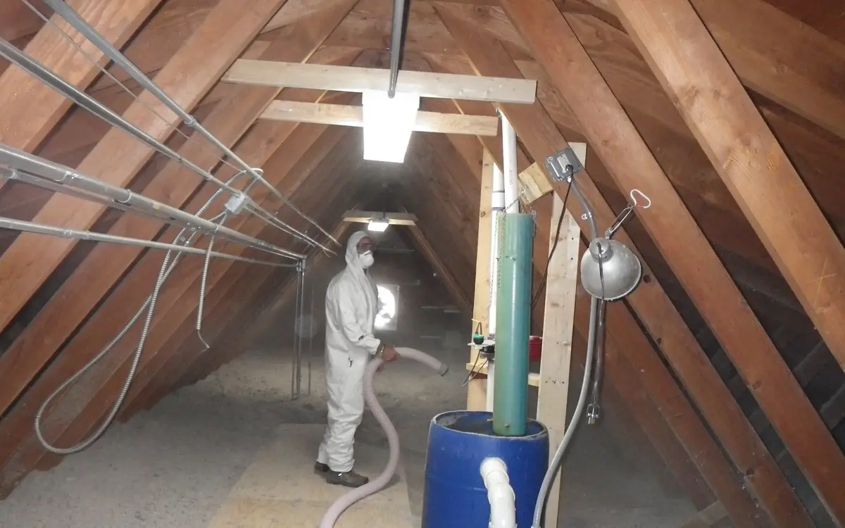
Loose fill needs bag count and depth agreed before the machine starts. Deduct the equipment platform and any area left deliberately for storage, add the perimeter you cannot fill to full depth, and stage bags so hose reach covers the far corners without a mid-job relocation. Set depth rulers on the framing at intervals, visible from the hatch, before blowing rather than after.
What the bill of materials looks like in section
- Blown fill to settled depth — the largest line on the order and the last decision on the list; bag count and settled thickness both come off the coverage chart, and hitting one without the other means the chart was ignored Blown-In Insulation Bag Count Calculator
- Unfaced batts across the joists — run perpendicular so they bridge the framing, cut slightly long for a friction fit, and never given a second facing pointed up into the attic Insulation Batt Calculator
- The sealed ceiling plane — rigid covers over the big chases, sheet metal where a flue needs clearance, sealant at every top plate and annular gap - quantified from the bypass schedule, never from floor area
- Joists and the ceiling below — the surface every one of those penetrations passes through, and the reason measured on-centre spacing beats the nominal figure when batts are ordered Drywall Calculator
With the depth fixed, size the batt order against measured bay spacing and the area actually being covered, not the gross ceiling footprint.
SettingsSettings for this calculation
The standard allowance most suppliers and estimating guides assume for ordinary work.
The length of the wall, floor, or attic area to insulate.
The width of the area to insulate.
The square footage one package covers, printed on the product label.
Extra material for cuts around obstructions (pipes, wiring, joists).
Estimated insulation batt needed
12 packages
- Area to insulate
- 1,014 sq ft
- Area with waste factor
- 1,115.4 sq ft
They open the calculator with your figures already in it
Insulation Batt Calculator: 12 packages — shown in imperial, US market. The link sets both, so the result they see is the one on your screen.
Estimated cost — your price
This site holds no price list for this material — local prices vary too much to publish honestly. Enter your supplier's price and the result is costed with it.
What this calculation does not cover
- This counts area against the coverage printed on your package. It does not check that the batt width suits your framing spacing or that the batt thickness fits the cavity depth — a 16 in (406 mm) batt in bays framed at 24 in (610 mm) centres leaves gaps that no package count corrects.
- No R-value enters the calculation. Nothing here tests the finished assembly against the R-value your climate zone and local code call for, and no allowance is made for heat flow through the framing members themselves, which conduct more than the cavity beside them.
- The area is the plain rectangle you enter. Nothing is deducted for windows, doors or the attic hatch, and nothing is set aside for the areas that must stay clear — recessed lights, flues and chimneys, and the eave gap soffit ventilation needs. Those clearances come from the manufacturer's instructions and local code, not from this count.
- The waste factor is a flat percentage of the whole area, not a cutting plan. Irregular bays, hips and valleys, and heavily obstructed framing produce short offcuts that waste far more than a percentage of the total suggests.
- This is a purchase quantity, not an energy or compliance calculation. It says nothing about air sealing — batts do not stop air leakage — nor about which way a faced batt's vapour retarder must face, which depends on your climate.
What bites back: moisture, heat and buried hazards
Some things in an attic bite back, and every one of them outranks the insulation work itself. Vermiculite of uncertain origin may contain asbestos: stop, disturb nothing, and have it tested before anyone moves material. That decision belongs to the owner and a qualified assessor, not to the crew already on the roof.
Moisture problems get fixed before insulation, never after. Bath and kitchen fans terminating into the attic, or into a soffit that draws straight back in, will frost a roof deck and wet new material the first cold snap. Dark staining on sheathing, rusted nail points and damp compressed insulation are all telling you the ceiling plane leaks air, which loops straight back to the first-ranked item.
Heat sources need clearances honoured to the listing on the appliance or vent, not to a number remembered from another job; chimney and vent clearances are governed by NFPA 211 Standard for Chimneys, Fireplaces, Vents, and Solid Fuel-Burning Appliances together with the listing itself. Non-IC-rated recessed luminaires cannot be covered at all, so either dam them off with sheet metal to the required clearance or swap them for listed IC-rated airtight housings.
Electrical work carries hard limits. Junction boxes must stay accessible and cannot be buried; knob-and-tube wiring is prohibited from being covered with insulation in many jurisdictions, and where it exists the wiring decision precedes the insulation decision entirely. Surface burning characteristics of the material itself are tested to ASTM E84 Standard Test Method for Surface Burning Characteristics of Building Materials, worth checking on any loose-fill product heading near a heat source.
Proving the order was actually followed
Proof that the ranking was followed has to be captured before it gets buried. Photograph every sealed bypass with something in frame for scale and location, because once the blow is done the only visible evidence left is depth.
Retest what you changed. A blower door before and after quantifies the first-ranked item; infrared scanning across a decent indoor-outdoor temperature difference finds missed bays and compressed patches, and site leak detection practice is described in ASTM E1186 Standard Practices for Air Leakage Site Detection in Building Envelopes and Air Barrier Systems. Combustion appliances get a worst-case depressurisation test after tightening, every time, no exceptions.
Leave the record in the attic. Depth rulers standing at the finished level, an installation certificate stating material, rated resistance, thickness and coverage where the jurisdiction requires one, and a hatch cap that closes onto its gasket - those three tell the next person what was done here, and they let anyone verify the ranking held without opening a single bag.
Fix the number the retest has to beat before the fan goes in the door, because a reading with nothing to measure it against proves only that air moves.
The total conditioned (heated/cooled) floor area of the building.
The average ceiling height across the conditioned space.
Your airtightness goal, e.g. from an energy code requirement or certification program.
Target CFM50
432 CFM50 (target maximum)
Your actual blower door test result should come in at or below this target — this is the inverse of the Air Changes Per Hour Calculator, useful for setting a goal before construction or air sealing work rather than evaluating a completed test.
- Building volume
- 8,640 ft³
They open the calculator with your figures already in it
Blower Door CFM50 Target Calculator: 432 CFM50 (target maximum) — shown in imperial, US market. The link sets both, so the result they see is the one on your screen.
Add the equipment this sizes
This result is a specification — 432 CFM50 (target maximum) — not a quantity. Put the thing it sizes into your project: how many, what you call it, and your supplier’s price.
What this calculation does not cover
- Building volume here is nothing more than floor area multiplied by average ceiling height. That ignores the thickness of intermediate floor assemblies, flattens stairwells and double-height spaces into an average, and omits any conditioned basement or attic whose area you did not enter. The target moves in direct proportion to the volume, so a volume measured ten per cent differently from the tester's gives a CFM50 limit ten per cent different — agree the volume basis with whoever will run the test before you build to this number.
- Nothing here defines the tested envelope: whether an attached garage, an unheated basement, a conditioned crawl space or a plant room sits inside or outside it. That single decision changes both the volume in the denominator and the leakage the fan has to move. Two people can test the same building to two different ACH50 figures purely by drawing the boundary in two different places.
- ACH50 normalises leakage against volume. UK and much European testing, and some North American programmes, instead specify air permeability or leakage per unit of envelope area. This page never asks for envelope area, so a target handed to you in those terms cannot be met by hitting this CFM50 figure.
- The number assumes a properly conducted test at 50 Pa. It carries no correction for wind, stack effect or baseline pressure, no averaging of a depressurisation result against a pressurisation one, and no allowance for how the building is prepared — which trickle vents, flues, extract fans and drain traps get sealed and which are left as found. Those are the usual reasons two tests of the same building disagree.
- This is a target airflow, not a ventilation or combustion-air check. A building tightened towards a low ACH50 needs mechanical ventilation sized and commissioned for it, and any open-flued or naturally aspirated appliance inside the envelope needs its own combustion air and spillage assessment. Hitting this figure says nothing about either, and those are the parts that carry a safety consequence.
Attic take-off, in rank order
Price the holes before the field: the list below follows the loss ranking, so the last line is the biggest order and the last decision.
- Bypass schedule (count and rough area of every ceiling penetration) — Chases, dropped soffits, fan and luminaire housings, top-plate joints. Drives sealant, rigid board and sheet metal quantities.
- Baffles, one per vented rafter or truss bay — Plus fasteners. Count bays on the plan, then verify at the eave - blocked or missing bays are common.
- Eave blocking or dam stock — Height set by finished depth at the perimeter, limited by heel height. Note where full depth is unachievable.
- Hatch cap, weatherstripping and compression latch — Include a dam around the opening taller than the finished insulation depth.
- Field insulation: settled depth and bag count, or batt count at measured spacing — Deduct equipment platforms and agreed storage area. Set depth rulers before the machine starts.
- Verification kit — Blower door, infrared camera, combustion analyser for the worst-case depressurisation retest, and a camera for the pre-burial photo record.
Opens the calculators above on one screen with the dimensions from this article already filled in. Quantities only — this site publishes no price list, because local prices vary too much to publish honestly.