
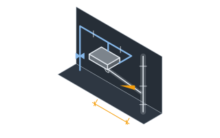
SettingsSettings for this calculationUS
The open cross-sectional area of the relief valve's discharge orifice.
Available from the backflow preventer manufacturer's relief valve data. Larger reduced-pressure assemblies typically have larger relief orifices.
An empirical factor accounting for orifice flow contraction and friction losses.
A sharp-edged orifice typically has a discharge coefficient around 0.6. Rounded or nozzle-shaped orifices can be higher.
The pressure head driving flow through the relief valve orifice, expressed as a water column height.
This is the differential pressure across the relief valve at the moment of full discharge, converted to an equivalent height of water.
Relief valve discharge flow
36.8 gal/min
Confirm the actual relief valve orifice area and discharge coefficient from the specific backflow preventer manufacturer's data — this is a general orifice-flow estimate, not a substitute for the manufacturer's rated relief capacity.
- Discharge velocity
- 913.37 ft/min
They open the calculator with your figures already in it
Backflow Preventer Relief Valve Discharge Calculator: 36.77 gal/min — shown in imperial, US market. The link sets both, so the result they see is the one on your screen.
Show calculation logicHide calculation logic
How this was calculated
Formula source(s)
- Discharge flow = orifice area × discharge coefficient × √(2×g×head), the standard orifice discharge equation applied to a relief valve opening, used to size the air gap fitting or floor drain that must handle the preventer's full relief discharge
Inputs used
- Relief Valve Orifice Area
- 0.78 in²
- Discharge Coefficient (Typically ~0.6 for a Sharp-Edged Orifice)
- 0.6
- Available Pressure Head
- 10 ft
Intermediate steps
- Discharge velocity
- 913.37 ft/min
Confidence note: Confirm the actual relief valve orifice area and discharge coefficient from the specific backflow preventer manufacturer's data — this is a general orifice-flow estimate, not a substitute for the manufacturer's rated relief capacity.
What this calculation does not cover
- Takes the head as given and does not derive it. During a genuine relief event the driving head is the supply-side pressure at that instant, not a static column — a 70 psi (483 kPa) main is about 50 m (164 ft) of water, not the 3 m (10 ft) the field opens on — and because flow goes with the square root of head, an assumed head that low understates the discharge by roughly a factor of four.
- Says nothing about how the discharge is piped. Relief from a reduced-pressure assembly must reach the drain through an air gap and never a direct connection — hard-piping it into the waste system rebuilds the exact cross-connection the assembly was installed to prevent, and it also means a relief event pushes into the drain instead of showing itself on the floor where someone notices it.
Add the equipment this sizes
This result is a specification — 36.8 gal/min — not a quantity. Put the thing it sizes into your project: how many, what you call it, and your supplier’s price.
Computed in your browser — nothing you enter is uploaded. Presented in US customary units and US trade terminology. Where a formula follows a published standard, that standard and its edition are cited beside it on this page; where none governs, the page says so. Local amendments override model codes — verify against the code in force where you build.
Sources checked 2026-09-06 · in the site-wide review of 2026-09-06 · v1.0.1
Regulatory standards & verification citations1
- Discharge flow = orifice area × discharge coefficient × √(2×g×head), the standard orifice discharge equation applied to a relief valve opening, used to size the air gap fitting or floor drain that must handle the preventer's full relief discharge
Cite this page
Your workspace
Most jobs need more than one number. Add the calculators you need next and they open right here, underneath this one — your figures stay on screen and nothing is lost to a page change.