
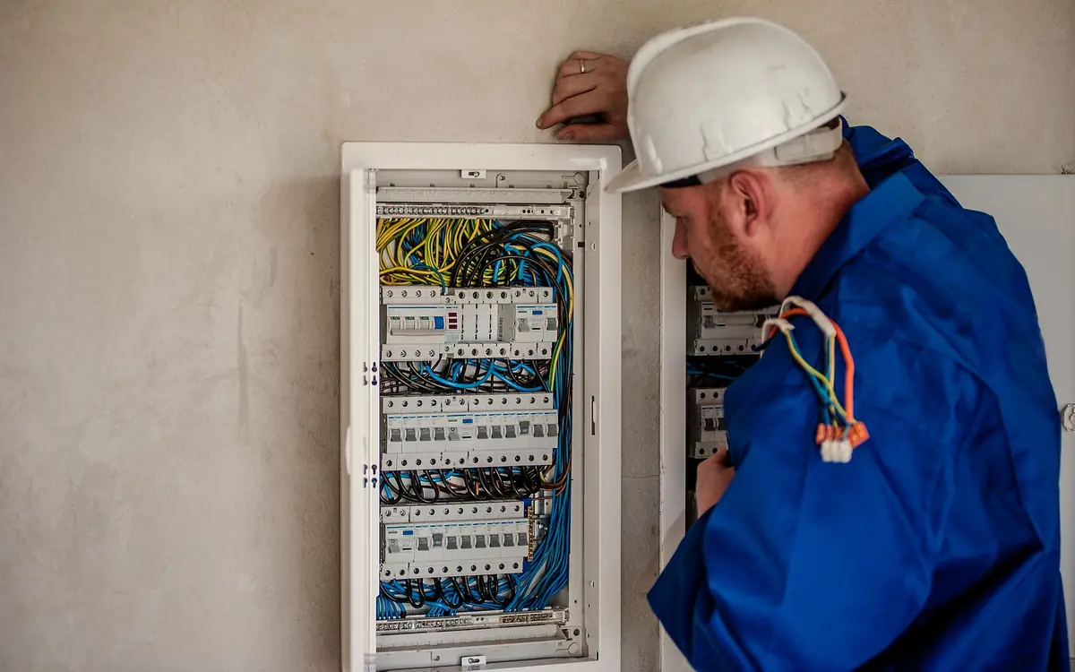
The Fuse Is the Distributor's, and It Is Not a Capacity
Start at the intake with a torch and a camera. On a British service you are reading a moulded carrier with a rating on it, a fuse link inside that carrier with its own rating and standard marking, and a wire-and-lead seal across the assembly. Domestic service cut-out links are made to BS 88-3, which superseded the BS 1361 Type II links still sitting in plenty of older intakes; sixty, eighty and one hundred amperes are what you will normally meet. On a North American service the equivalent reading is the utility transformer and service conductors on one side and the rating of the service disconnecting means on the other, the latter governed by NFPA 70 Article 230.
The carrier and the link are separate ratings and they disagree more often than people expect — a hundred-ampere carrier will happily hold a sixty-ampere link, and on many designs the link rating cannot be read at all without withdrawing the carrier. Do not withdraw it. That assembly is the distributor's property, the seal is there for a reason, and in Great Britain the whole arrangement sits under the Electricity Safety, Quality and Continuity Regulations 2002 and the distributor's own access policy. A booked fuse pull costs very little set against what happens to an installer found working inside sealed equipment.
The more useful thing to understand is what the fuse is for. It is protecting the service cable against fault current, not rationing the household. Its time-current characteristic is drawn to clear faults, which means a sustained modest overload can persist for a very long time without operating anything — so a house that has been fine on sixty amperes for thirty years has told you nothing whatever about whether that service cable has been running warm for a decade. The absence of a blown fuse is not evidence.
The reverse error is commoner and more expensive. A hundred-ampere fuse is not a promise of a hundred amperes. Behind it sit a service cable of unknown size, a main under the pavement shared with the rest of the street, and a transformer, and every one of those was planned on an after-diversity maximum demand — a per-property figure of a few kilowatts, set out in each distributor's own network design standard and its licence-mandated long term development statement, and ask for the current one rather than quoting a number you remember. Nothing in that planning chain assumed your customer would draw the twenty-three kilovolt-amperes a hundred-ampere single-phase service could theoretically deliver, and the whole street's worth of that assumption is what a wave of heat pumps is currently testing.
Record all of it before you leave. You will be asked for every line of it, a second visit is unpaid, and each of these readings is silent about something people routinely assume it covers.
| What you are looking at | What to write down | What it is silent about |
|---|---|---|
| Cut-out carrier and fuse link | Carrier rating, link rating and standard marking, seal condition, manufacturer | The size of the service cable behind it, and the spare capacity in the street |
| Service entry | Underground or overhead, sheath condition at the gland, apparent age of the termination | The conductor size, which only the distributor's own record will confirm |
| Earthing terminal | Whether the distributor provides an earth, how it is labelled, the conductor size leaving it | Whether the same arrangement will still be offered once the service is replaced |
| Meter and tails | Whole-current or transformer-operated metering, tail size, presence of an isolator | Which supplier and meter operator hold the appointment, which the customer must ask |
| Meter enclosure and position | Internal dimensions, spare width, whether a larger cut-out and meter would fit | Whether the distributor will accept that position for the replacement intake |
| Supply number | The full supply number from the bill or the meter, distribution area digits included | Anything about capacity; it identifies the connection point and nothing more |
The Loads That Started the Conversation
Three loads arrive together in this decade and none of them behaves like the appliances the service was sized around. The heat pump modulates: for most of the year it draws a fraction of its nameplate, and then on the coldest morning of the year the compressor is at maximum and the resistive backup element energises on top of it. The figure you want is the maximum running current the manufacturer publishes — Mitsubishi Electric, Daikin and Vaillant all state it in the installation manuals for their domestic ranges, along with a starting current — and not any number derived from the heat output on the brochure.
The induction hob's nameplate is the arithmetic sum of every zone at boost, a condition that occurs in a laboratory and not in a kitchen. Nearly every hob sold now has a power limitation setting in its installation menu, stepping the total down to suit a smaller circuit, and configuring it is an entirely legitimate way to reduce the connected load. It is legitimate on one condition: the setting is recorded on the certificate and the householder is told what reversing it would mean, because an assessment resting on a menu option nobody wrote down expires the first time the appliance is serviced.
The charge point is the simple one to characterise and the hardest one to accommodate — full configured current, flat, for hours, on the same winter evenings as everything else. It needs no diversity argument because it does not behave diversely.
Coincidence is the whole question. Individually all three fit; the interesting number is what happens at half past six on a January evening with the hob at three zones, the heat pump in defrost with its backup on, and the car plugged in. Before any of that reaches a whole-house figure, though, each new circuit has to stand on its own against the continuous-load rule, because a service upgrade fixes nothing about a branch circuit that was already at its limit.
Take each new load on its own first — the hob at its configured limit, the heat pump with the backup element energised, the charger at its set current — and see how much of that circuit is genuinely spare. This runner applies the North American continuous-load rule to a 120 or 240 volt circuit on a 15 to 50 ampere breaker, so read the percentage rather than the amperage if your circuit is a British 32 ampere one at 230 volts. Either way the point is the same: a circuit already at its continuous ceiling is not a problem a bigger incoming fuse solves.
The amp rating printed on the breaker in your panel.
Most household outlets in North America are 120V; large appliances (dryers, ranges, EV chargers) are often 240V.
The sum of the wattage of everything plugged into this circuit at once.
Current draw
10 A
- Total connected load
- 1,200 W
- Safe continuous limit (80% rule)
- 16 A
- Safe continuous limit
- 1,920 W
- % of safe continuous capacity used
- 62.5 %
They open the calculator with your figures already in it
Electrical Circuit Load Calculator: 10 A — shown in imperial, US market. The link sets both, so the result they see is the one on your screen.
Add the equipment this sizes
This result is a specification — 10 A — not a quantity. Put the thing it sizes into your project: how many, what you call it, and your supplier’s price.
What this calculation does not cover
- ONE circuit, not the panel. Whether the service and the panel can carry everything together is a separate calculation under the code's demand-factor rules, and a house full of individually compliant circuits can still overload its supply.
- Says nothing about the WIRE. Conductor ampacity is set by the conductor, its insulation, the ambient temperature and how many current-carrying conductors share a raceway — a breaker rating does not guarantee the cable behind it, and a correctly sized breaker on undersized cable is the dangerous combination.
- Voltage drop over the run is not checked here. A circuit inside its current limit can still deliver too little voltage at the far end, which is a separate calculation.
- Motor and compressor loads draw several times their running current at start-up. Nameplate watts describe the running condition and understate what the breaker sees on a cold morning.
- The 80% figure applies to CONTINUOUS loads — three hours or more at full draw. A load that is genuinely intermittent may use more of the breaker's rating, and which of the two a given appliance is can be a judgement.
Code thresholds this tool can check
Code thresholds this tool can check
Checked for United States. Each check below names the body that published the limit it uses. Switching market re-runs them. This is not a code review and has no official standing.
These checks cover only the specific numeric limits listed below. They are not a complete code review: fire separation, egress, structural capacity and accessibility provisions are outside their scope, and only the handful of local amendments offered in the selector are modelled — your municipality may have others. Passing every check here does not make a design compliant. Final approval rests with your local building authority.
The Figure the Application Form Wants
The form does not ask what the property draws. It asks what capacity you want the network to reserve, which is a different question with a different answer, and confusing the two is how applications come back with queries. The reserved figure has to cover the worst case the installation can present, because the network is committing conductors and transformer capacity against it for the life of the connection.
Build it the way an inspector would recognise. The standard method assembles a general lighting allowance from floor area, the small-appliance and laundry circuits at their fixed values, the nameplate ratings of the fixed appliances, and then applies the published demand factors — NFPA 70 Article 220 in North America, BS 7671 Part 3 read with the maximum demand and diversity appendix of the IET On-Site Guide in the United Kingdom, the maximum demand appendix of AS/NZS 3000 in Australia and New Zealand. Whichever document you work from, note which one it was next to the number. The interesting comparison is not between your figure and the fuse; it is between your figure and the few kilowatts per property the distributor's own planning assumed, and that gap is what a reinforcement decision is made in.
Ask for what the installation needs and resist the temptation to take the largest option on the drop-down. On a constrained network an inflated request is what converts a straightforward service alteration into a reinforcement scheme with a reinforcement timetable, and in some charging regimes reserved capacity carries a standing cost the customer will meet every year. Under-asking is worse in a different way: coming back for another twenty amperes in two years is a second application, a second excavation and a second set of fees, none of which anybody budgeted.
Assemble the whole-dwelling figure before you fill anything in. This one runs the NFPA 70 Article 220 standard method — floor area, small-appliance and laundry circuits, fixed-appliance nameplate, then the demand factor — so take it as the worked shape of the calculation rather than as a British answer; a United Kingdom application wants the same assembly run through the On-Site Guide diversity appendix. Either way it is the number you will be setting against the distributor's own per-property planning assumption.
The total livable floor area of the dwelling used for general lighting load.
20A kitchen/dining small-appliance circuits, each counted at 1500 VA.
Dedicated 20A laundry branch circuits, each counted at 1500 VA.
Sum of the nameplate VA for fixed appliances such as the water heater, range, oven, and dryer.
The nominal service voltage supplying the dwelling.
Estimated required service amperage
38 A
This is a SIMPLIFIED illustrative version of the NEC 220 standard method, omitting several real-world factors (HVAC load, EV chargers, largest motor load addition, optional calculation method). Fixed appliances are carried at 100% because this page takes a VA total and not a count; 220.53 permits 75% where four or more fastened-in-place appliances are present, and a range or a dryer has its own table (220.55, 220.54) that this does not apply. It is NOT a substitute for a complete NEC Article 220 load calculation performed by a licensed electrician, which determines your actual required service size and is required for permitting. Always round up to the next standard breaker/service size (100A, 125A, 150A, 200A) and consult your electrician.
- Total connected load (before demand factor)
- 13,030 VA
- General lighting and receptacles, after the 220.42 factor
- 5,110.5 VA
- Fixed appliances, at 100%
- 4,000 VA
- Demand load
- 9,110.5 VA
They open the calculator with your figures already in it
Home Electrical Service Panel Amperage Sizing Calculator: 37.96 A — shown in imperial, US market. The link sets both, so the result they see is the one on your screen.
Add the equipment this sizes
This result is a specification — 38 A — not a quantity. Put the thing it sizes into your project: how many, what you call it, and your supplier’s price.
What this calculation does not cover
- Amps are not spaces. This sizes the SERVICE and says nothing about the panel's physical capacity — a dwelling can sit comfortably inside 100 A of calculated demand and still need a new panel because every breaker position is taken, the busbar is rated below what is being added to it, or the enclosure will not accept the breaker type the new circuits require. Panels get replaced for spaces at least as often as for amperage.
- The amperage is where the rest of the sizing starts, not where it ends. Service-entrance conductors, the grounding electrode conductor, the meter base, the mast or lateral and the utility's own drop or transformer all follow from this number and none of them fall out of it — and a dwelling service gets its own conductor allowance under NEC 310.12 rather than the general ampacity table, so the wire for a 200 A house is not the wire that table would give it.
- One dwelling unit. A second unit on the same service, an ADU, or a detached garage or workshop on a feeder are not added by piling their loads into these boxes: a multifamily service runs through 220.84's own demand table, and a feeder to an outbuilding is calculated as its own load under 220.40. Stacking two dwellings into this page understates both of them.
Kilowatts on the Nameplate, Kilovolt-Amperes on the Offer
Everything the customer owns is labelled in kilowatts. Everything the network sells is denominated in kilovolt-amperes. That is not a formatting preference: transformer windings and buried conductors heat according to the current passing through them, current follows apparent power, and so the quantity the distributor has to ration is the one that includes the reactive component it gets no revenue for.
For an all-electric house the two figures nearly coincide, because resistive heating, immersion elements and modern power supplies present something close to unity. A workshop does not. A compressor, a welding set and a couple of motor-driven machines pull the displacement power factor down, and inverter-driven equipment can present a respectable displacement figure while its harmonic content still inflates the current the conductor actually carries. IEC 61000-3-2 and IEC 61000-3-12 set what equipment may inject; the consequence at the intake is that the true power factor and the one on the specification sheet are not always the same number.
The conversion trips people in one direction specifically. Going from a kilowatt load schedule to the kilovolt-ampere capacity you must request means dividing by the power factor, and dividing makes the number bigger — an eighty-kilowatt workshop load at a power factor of 0.8 needs a hundred kilovolt-amperes reserved, not eighty. Where the constraint or the tariff is expressed in kilovolt-amperes, correction equipment genuinely buys capacity back, which is occasionally a cheaper answer than the upgrade the customer came to ask for.
This is the direction that matters on an application: a load schedule in kilowatts, a capacity request in kilovolt-amperes, and a division that makes the number larger. The runner is fixed at a power factor of 0.8 — the mixed-load planning convention, and the figure behind the eighty-kilowatt workshop above — so for any other power factor take the result as the shape of the sum and divide by your own.
The real power demand in kilowatts.
The load's power factor: 1 for resistive heating, lower for motors. It opens on 0.8, the factor three-phase generator sets are rated at; a single-phase set is rated at 1.
Apparent power
100 kVA
kVA = kW ÷ power factor. The kvar row is the reactive part the supply carries on top of the working current; a generator has to be checked against its kVA as well as its kW, taking whichever binds first. Motor inrush frequently determines generator size rather than running load, so check starting current separately.
- Real power entered
- 80 kW
- Power factor applied
- 0.8
- Reactive power, kW × tan(arccos PF)
- 60 kvar
They open the calculator with your figures already in it
kW to kVA Calculator: 100 kVA — shown in imperial, US market. The link sets both, so the result they see is the one on your screen.
Add the equipment this sizes
This result is a specification — 100 kVA — not a quantity. Put the thing it sizes into your project: how many, what you call it, and your supplier’s price.
What this calculation does not cover
- The answer scales inversely with the power factor entered, and the field opens on 0.8 for a set's badge, not because any load runs there. Three-phase generator sets are conventionally rated at 0.8 — Cummins lists the C20D6 at 25 kVA and 20 kWe — while single-phase sets are rated at 1, where kVA and kW are the same number. A motor-heavy site below 0.8 needs more kVA than the opening answer shows, and a corrected or largely resistive one needs less.
- This is a unit conversion, not a load calculation. It takes the kW figure you type at face value and applies no diversity, no demand factors and no maximum-demand assessment, so it does not stand in for a proper load assessment before ordering a supply, transformer or generator set.
- Steady-state only. Motor inrush, step-load acceptance and transient voltage dip are not modelled, and on a generator these frequently set the machine size well above the running kVA calculated here.
- No voltage, current or phase comes out of this. The result does not size conductors, protective devices or switchgear; the current at a given voltage, single-phase or three-phase, is a separate step on the watts, amps and kVA page.
- Distorting loads such as variable-speed drives, UPS and some LED and IT supplies draw harmonic current that a single power factor does not describe. Nothing here derates the machine for that content, or for altitude and ambient temperature on a generator.
Sizing a generator, transformer or supply from a known load means working from real power back to apparent power, because it is apparent power that the conductors and switchgear actually have to carry. Dividing by the power factor does that, and the worse the power factor the larger the required capacity for identical useful output — current flows and heats cables whether or not it is doing work. The field opens on 0.8, the factor three-phase sets are conventionally badged at — a single-phase set is rated at 1, its kVA and kW the same number — and the load's own figure belongs in it once it is known. Two checks belong alongside the arithmetic. A generator should be assessed against both its kW and its kVA rating, taking whichever binds first. And motor starting current, which can be several times the running figure, frequently sets the machine size regardless of what the steady-state calculation says.
When the Answer Comes Back Three Phase
The reply is frequently not the bigger single-phase service that was asked for. Where the main in the street is already three-phase and the existing service is simply a spur taken off one of its phases, giving the property all three is often the distributor's cheapest route to more capacity — the trench is the same trench and the cable is barely larger. In Great Britain that turns twenty-three kilovolt-amperes on a single hundred-ampere phase into roughly sixty-nine across three at four hundred volts between lines, which is more headroom than a domestic customer will ever use.
It changes a great deal downstream. A three-phase board with a three-phase main switch, tails per phase plus a neutral, a physically larger intake, and — this one catches people — a different meter. In Great Britain whole-current metering runs out at a hundred amperes per phase; above that the connection moves to transformer-operated metering with a current transformer chamber ahead of the meter, which is a materially different intake enclosure and a materially different price. On the workshop side the gain is real: three-phase machines start properly, and the rotary converter or the drive that has been standing in for a missing phase can come out.
The vocabulary does not travel. In North America a residential three-phase supply is unusual, and a shop building typically receives 208Y/120 or 480Y/277 under ANSI C84.1. Two hundred and eight volts is not two hundred and forty, and equipment rated for a 240-volt single-phase supply run instead across two legs of a 208-volt system delivers materially less than its rating — resistive heating loads suffer most, and the discovery is normally made after the equipment is installed.
Whatever the arrangement, ask two questions before accepting. What becomes of the existing single-phase circuits on the changeover day, and how long the property is without a supply while it happens. A three-phase board in a house means four hundred volts is present between adjacent ways in equipment most people who ever open it will assume is a 230-volt board, so labelling, segregation and the schedule you leave behind matter more here than they do on the single-phase job.
Line voltage, current per phase and power factor give what a three-phase service actually delivers. Set that against the machine schedule for the workshop before agreeing to the offer, not after the switchgear is ordered.
The line-to-line voltage of the three-phase system.
The current draw per phase, in amps.
The load's power factor — 1.0 is purely resistive, motors are typically lower.
Real power
35.33 kW
- Apparent power
- 41.57 kVA
They open the calculator with your figures already in it
Three-Phase Power Calculator: 35.33 kW — shown in imperial, US market. The link sets both, so the result they see is the one on your screen.
Add the equipment this sizes
This result is a specification — 35.33 kW — not a quantity. Put the thing it sizes into your project: how many, what you call it, and your supplier’s price.
What this calculation does not cover
- BALANCED loads only. The square root of three assumes the three phases carry equal current; an unbalanced load puts current in the neutral and the phase currents stop being interchangeable, so a single measured current no longer describes the system.
- The power factor entered has to be the TRUE power factor, not the displacement factor alone. Variable-speed drives, LED drivers and switched-mode supplies draw harmonic current that adds to the apparent power without adding real power, and a meter reporting only displacement will flatter the answer.
- Sizing conductors and protection from this figure means going through current, not kilowatts: ampacity, voltage drop, the protective device and any derating for grouping or ambient temperature are separate calculations, and the kW here is an input to none of them directly.
- Motor loads draw far more than their running current at start-up — several times, depending on the starting method — and it is the starting condition that sizes the protection and stresses the supply.
- Harmonic current also loads the neutral in a way the phase figures do not show. On a three-phase supply with many single-phase electronic loads, the triplen harmonics add rather than cancel in the neutral, which is why a neutral sized to match the phases can still run hot.
A Better Supply Raises the Fault Level
The thing that makes an upgraded service good is exactly the thing that makes it more dangerous at the origin. A larger conductor, a shorter run, a nearer or larger transformer — every one of those lowers the source impedance, and lower source impedance means a higher prospective short-circuit current at the cut-out. The consumer unit downstream, its main switch, and the conditional short-circuit rating of the devices inside it were all selected against whatever the old service could deliver.
So measure the prospective fault current and the external loop impedance after the changeover rather than reusing the survey figures, and record both. Distributors in Great Britain declare a maximum prospective fault current for a domestic service — sixteen kilo-amperes is the figure most commonly quoted at the origin — and an assembly whose rating was justified by a comfortable measurement taken on the old supply is a non-compliance that nothing in the installation's behaviour will ever reveal.
The Earthing Arrangement Comes With the Offer
A new service can arrive with a different earthing arrangement from the one it replaced, and this is not always flagged. A property that never had a distributor earth may be offered one; a property that had a combined neutral and earth arrangement may find it withdrawn, particularly where the replacement service comes in overhead or where the distributor's policy for that class of connection has moved on. Either change lands on the installation designer, not on the distributor.
The consequences run through the whole protective system. Main protective bonding conductor sizes are set by the earthing arrangement and the size of the supply neutral, not by the load — the requirements where a protective multiple earthing terminal is provided are larger, and BS 7671 Chapter 54 read alongside Energy Networks Association Engineering Recommendation G12 is where that comes from; NFPA 70 Article 250 and its grounding electrode conductor table are the counterpart on the other side of the Atlantic. A new service therefore means going back to the gas and water bonds and the structural steel, which in a house of any age means finding a single undersized conductor clamped somewhere convenient rather than where the service enters.
Where the distributor declines to provide an earth at all, the installation needs its own electrode, and that is a redesign rather than an adjustment: earth fault loop impedance is now dominated by the electrode resistance, every final circuit depends on residual current protection for disconnection, and the soil the electrode is going into is a variable nobody chose. Price that possibility before the offer is accepted, because discovering it afterwards makes it the customer's surprise instead of a line in the quotation.
Trench, Meter Box, and Who Digs What
Almost every offer splits the physical work at a point of connection: the distributor works up to it, and everything on the customer's side is the customer's to provide. Excavation, ducting, backfill, reinstatement and the meter enclosure are the usual customer-side items, and taking the self-dig option is normally the single largest saving available on the whole job — provided the groundwork is done to their specification and not to a general idea of what a trench looks like.
That specification is prescriptive and it is worth having in writing before anyone hires a machine. Depth of cover, bedding material, warning tape, duct diameter and colour, minimum bend radius, a draw rope left in place, and jointing pits wherever the route changes direction enough to make the pull unreasonable. Have the open trench inspected before it is closed. A trench backfilled early on the assumption that it was obviously fine is a trench that gets reopened, and the second excavation is nobody's contractual obligation but the customer's.
Land the customer does not own stops jobs dead. A service crossing a neighbour's garden, a shared drive, a farm track or an access strip requires a wayleave or an easement, and that is a legal instrument on a legal timescale measured in months rather than weeks. On rural connections it is the commonest reason a scheme stalls after the offer has been signed and the money paid.
Settle the intake position early, because it decides more than it looks like it decides. Moving a meter from an internal cupboard to an external box is frequently bundled into the upgrade, and where the intake ends up sets the tail lengths, the board position, the route of the main protective bonding, and whether the consumer unit finishes somewhere with the clear working space the rules in force require in front of it.
- Walk the route with the distributor's engineer before anybody prices the groundwork.
- Establish the point of connection on the ground and confirm in writing who owns each side of it.
- Get the duct, depth, bedding and reinstatement specification in writing and read it before hiring plant.
- Establish ownership of every metre of the route, and start the wayleave or easement the same week if any of it is not the customer's.
- Hand-dig at every crossing with an existing service and record the depth and separation you found.
- Have the trench inspected and photographed open, dimensioned from two fixed points on the building.
- Leave the duct roped, sealed at both ends and drawn through, and fit the enclosure before the energisation date.
Three Organisations, One Energisation
The connection involves three separate parties and only one of them is the distributor. The distributor owns the service cable and the cut-out. The supplier holds the customer's account. The meter operator, appointed by the supplier rather than by the customer, owns and fits the meter. Nothing coordinates the three by default, and the customer is the only person with a contractual relationship with all of them.
The failure this produces is predictable enough to plan around: a new service energised and sealed, and no meter, because the metering appointment was never raised. A change in phase count almost always means a new meter, sometimes a new supply number, and always a fresh appointment booked through the supplier — who will ask the customer for it and not you. Raise it at the same time the offer is accepted, not when the distributor has finished.
Sequence your own work to be genuinely ready. Tails of the right size and length, an isolator where one is needed, the board fitted, the earthing and bonding complete and tested, and the installation certificate available. The energisation visit is short and it is not a fault-finding visit; an installation still open when the engineer arrives becomes a second appointment at a lead time nobody quoted for.
What the Next Person Needs From You
Leave a record that survives you. The offer reference and the capacity requested; the new fuse rating with its standard marking; the earthing arrangement actually provided and whether it changed; the prospective fault current and external loop impedance measured after energisation; the duct route dimensioned from two fixed points; and every configured setting — the hob's power limit, the heat pump's backup element, the charge point's output — that the demand assessment quietly depends on. Whoever adds a battery to this property in three years is either building on that or repeating all of it.
Then be straight with the customer about what has and has not been bought. A reserved capacity is a commitment about this connection, not a statement about the street. If the network was already tight, the next few applications on the same main are the ones that get the conditional answers, and if the property is on the end of a rural spur then voltage at the far end — the range every distributor must hold under its own statutory obligation — may govern long before capacity does. Saying so on the day is a better conversation than having it after a complaint.
Settling the numbers before the form is filed
Nearly all of this is decided at the property with a torch and a camera, and the rest of it on a desk before anything is submitted. These are the lines that decide whether the answer comes back in a fortnight or in eighteen months.
- Carrier rating, link rating and standard marking, read at the cut-out — Photographed with the seal intact; the two ratings disagree often enough that recording only one is worthless.
- Whole-installation demand assembled by a named method — Write down which document supplied the demand factors, because the application will be queried against it and the note is free at the time.
- Manufacturer maximum running current for each new load — Heat pump with its backup element, hob at its configured limit, charger at its set output — not figures derived from heat output.
- Requested capacity converted to kilovolt-amperes at a real power factor — Divide, do not multiply; a workshop schedule in kilowatts always understates what has to be reserved.
- Phase count decision and its downstream cost — Board, main switch, meter type and whether whole-current metering still applies above a hundred amperes per phase.
- Ownership of every metre of the cable route — A wayleave or easement across a neighbour or a track is a legal timescale, and it is the usual reason a signed offer then stalls.
- Earthing arrangement offered with the new service — Bonding conductor sizes follow the arrangement rather than the load, and a withdrawn distributor earth is a redesign to be priced early.
Opens the calculators above on one screen with the dimensions from this article already filled in. Quantities only — this site publishes no price list, because local prices vary too much to publish honestly.