
SettingsSettings for this calculationUS
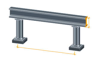
The I-beam's overall depth, measured outside-to-outside of the flanges.
Outside to outside, so it includes both flange thicknesses — the web height between them is this figure less twice the flange. Rolled sections are named by a nominal depth that is not the actual one: a nominal 12 in or 300 mm beam is rarely exactly that, and the section table's true depth is what belongs here.
The width of each flange.
Both flanges, since this treats the section as symmetric — which a rolled I-section is and a fabricated plate girder need not be. For a girder with unequal flanges, work each one's area out separately rather than averaging the two widths.
The thickness of each flange.
Some rolled series have a taper on the inner flange face and others are parallel; this treats them as parallel rectangles. That is close for a parallel-flange section and slightly light for a tapered one, which is part of why the answer lands a little under the catalogue weight.
The thickness of the web connecting the two flanges.
The other reason this reads under the catalogue figure is the root radius — the fillet where web meets flange holds real steel that a rectangle model ignores. Expect roughly one to two per cent light on a rolled section, and more on a small one where the fillets are a larger share of the area.
Weight per unit length
31.8 lb/ft
Simplified rectangular approximation omitting web-flange fillet area — for exact values, use the published AISC (or equivalent) shapes table for your specific designation.
- Cross-sectional area
- 9.33 in²
They open the calculator with your figures already in it
Steel I-Beam Weight-per-Length Calculator: 31.76 lb/ft — shown in imperial, US market. The link sets both, so the result they see is the one on your screen.
Show calculation logicHide calculation logic
How this was calculated
Formula source(s)
- Weight per unit length = cross-sectional area × steel density (7850 kg/m³); simplified I-shape area = 2×(flange width × flange thickness) + (depth − 2×flange thickness) × web thickness, omitting fillet area (a slight underestimate vs. published AISC tables)
Inputs used
- Overall Depth
- 11.75 in
- Flange Width
- 6 in
- Flange Thickness
- 0.5 in
- Web Thickness
- 0.31 in
Intermediate steps
- Cross-sectional area
- 9.33 in²
Confidence note: Simplified rectangular approximation omitting web-flange fillet area — for exact values, use the published AISC (or equivalent) shapes table for your specific designation.
What this calculation does not cover
- Both flanges are built from the single width and the single thickness you enter, doubled, so the figure describes a doubly-symmetric shape; a fabricated girder with a wider or thicker bottom flange has to be worked out as two separate flange areas and added, not averaged into one entry.
- Nothing here asks how long the beam is. The answer is the mass of one metre of section, so the piece weight that sets the crane class and the needle sizing comes from multiplying it by the actual stick length, and it reads identically for a 1 m (3.3 ft) stub and a 12 m (39 ft) span.
- The section is taken as constant from end to end. Copes, notches, web penetrations and castellated cells remove steel from a real member, while end plates, stiffeners, cleats, bolts, weld metal, primer, galvanizing and an intumescent film all add it back, and none of the four dimension fields can see any of that.
- The entry fields stop at 60 mm of flange thickness, 40 mm of web and 1.2 m of depth, and anything beyond is brought back to the limit with a notice. The heaviest jumbo column sections and deep fabricated plate girders sit outside that range, so what comes back for them is the weight of a smaller section than the one on the drawing; at the light end a web under 3 mm is lifted to 3 mm and reads heavy.
- Depth, flange and web go in and only a cross-sectional area comes out — those same dimensions are never assembled into a second moment of area. So nothing on this page states what the beam can span, carry or deflect, and two sections with the same weight per metre can differ widely in stiffness depending on how much of the steel sits in the flanges rather than the web.
Add the equipment this sizes
This result is a specification — 31.8 lb/ft — not a quantity. Put the thing it sizes into your project: how many, what you call it, and your supplier’s price.
Computed in your browser — nothing you enter is uploaded. Presented in US customary units and US trade terminology. Where a formula follows a published standard, that standard and its edition are cited beside it on this page; where none governs, the page says so. Local amendments override model codes — verify against the code in force where you build.
Sources checked 2026-09-05 · in the site-wide review of 2026-09-06 · v1.0.1
Regulatory standards & verification citations1
- Weight per unit length = cross-sectional area × steel density (7850 kg/m³); simplified I-shape area = 2×(flange width × flange thickness) + (depth − 2×flange thickness) × web thickness, omitting fillet area (a slight underestimate vs. published AISC tables)
Cite this page
Your workspace
Most jobs need more than one number. Add the calculators you need next and they open right here, underneath this one — your figures stay on screen and nothing is lost to a page change.