
SettingsSettings for this calculationUS
The lateral pressure the shaft enclosure is designed to resist.
Shaft enclosures are designed for a transverse pressure caused by lift piston effect, stack pressure or a smoke control system, and the figure is set by the project rather than by the wall. It is not a wind load; a shaftwall on the building perimeter has to be checked for both, at the greater of the two.
Centre-to-centre spacing of the C-H studs along the wall.
Spacing enters twice over. It sets the strip of wall each stud carries, so halving it halves the load per stud; but liner panel widths are fixed, so the spacing is usually decided by the panel rather than by the structure, and the height follows from it.
The stud's effective moment of inertia, from the manufacturer's table.
This is where stud depth and gauge enter the calculation. It is not a value you can derive from the nominal dimensions, because a cold-formed section's stiffness depends on which parts of it have buckled locally at the load in question, so it is published per depth and per gauge and must be read from the table for the exact stud specified.
The deflection limit the specification applies to this wall.
The limit follows the finish, not the fire rating. A shaft face left in bare liner and board is commonly held to L/240; a corridor face carrying tile, stone or a rigid coating is held tighter, because those finishes crack long before the framing is in any distress.
The floor-to-floor height you want to run this stud through.
Unsupported means exactly that: the distance between the top and bottom tracks, or between a track and a real intermediate brace. A ceiling grid, a duct hanger and a run of blocking are not lateral supports, and counting one as though it were is the commonest way a shaftwall ends up over-height.
Maximum unsupported height
18.9 ft
The proposed height uses 32% of the deflection allowance. This is the deflection-governed limit only — the manufacturer's tabulated limiting height is the lesser of this and a bending strength check, and for heavier gauges and higher pressures it is often strength that governs.
- Line load carried by one stud
- 10.44 lbf/ft
- Deflection at the proposed height
- 0.21 in
- Allowable deflection at the proposed height
- 0.65 in
- Deflection allowance used at that height
- 32.37 %
They open the calculator with your figures already in it
Shaftwall C-H Stud Limiting Height Calculator: 18.93 ft — shown in imperial, US market. The link sets both, so the result they see is the one on your screen.
Show calculation logicHide calculation logic
How this was calculated
Formula source(s)
- ASTM C645 (non-structural steel framing members) and ASTM C754 (installation of steel framing to receive gypsum panel products), which is where the practice of selecting studs from a published limiting-height table originates
- AISI S100 takes the modulus of elasticity of cold-formed sheet steel as 29,500,000 psi (203,400 MPa); the effective moment of inertia for a given C-H stud depth and gauge comes from the system manufacturer's own limiting height table
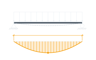
- Deflection-governed limiting height from elastic beam theory for a uniformly loaded simple span: setting 5wL⁴/(384EI) equal to L divided by the deflection ratio gives L = cube root of 384EI/(5wR)
Inputs used
- Design Transverse Pressure
- 5.22 psf
- Stud Spacing
- 24 in
- Effective Moment of Inertia I_eff (×10⁶ mm⁴)
- 0.45
- Permitted Deflection Ratio
- L/240
- Proposed Unsupported Height
- 13 ft
Intermediate steps
- Line load carried by one stud
- 10.44 lbf/ft
- Deflection at the proposed height
- 0.21 in
- Allowable deflection at the proposed height
- 0.65 in
- Deflection allowance used at that height
- 32.37 %
Confidence note: The proposed height uses 32% of the deflection allowance. This is the deflection-governed limit only — the manufacturer's tabulated limiting height is the lesser of this and a bending strength check, and for heavier gauges and higher pressures it is often strength that governs.
What this calculation does not cover
- Deflection only. Bending strength requires the effective section modulus and yield strength for the same stud, which are published alongside the moment of inertia and are not derivable from it.
- Treats the stud as a simply supported span between tracks. Slip track details, deflection heads and intermediate bracing all change the end conditions and the tabulated heights that go with them.
- The liner panel is not counted as contributing stiffness. Shaftwall liner is friction-fitted between the studs and is not composite with them, which is why manufacturers publish limiting heights against the stud alone.
Computed in your browser — nothing you enter is uploaded. Presented in US customary units and US trade terminology. Where a formula follows a published standard, that standard and its edition are cited beside it on this page; where none governs, the page says so. Local amendments override model codes — verify against the code in force where you build.
Sources checked 2026-08-30 · in the site-wide review of 2026-09-06 · v1.0.0
Regulatory standards & verification citations3
- ASTM C645 (non-structural steel framing members) and ASTM C754 (installation of steel framing to receive gypsum panel products), which is where the practice of selecting studs from a published limiting-height table originates
- AISI S100 takes the modulus of elasticity of cold-formed sheet steel as 29,500,000 psi (203,400 MPa); the effective moment of inertia for a given C-H stud depth and gauge comes from the system manufacturer's own limiting height table
- Deflection-governed limiting height from elastic beam theory for a uniformly loaded simple span: setting 5wL⁴/(384EI) equal to L divided by the deflection ratio gives L = cube root of 384EI/(5wR)
Which documents these citations point at
Standards referenced: ASTM C645, ASTM C754 (ASTM International, United States).
Cite this page
Your workspace
Most jobs need more than one number. Add the calculators you need next and they open right here, underneath this one — your figures stay on screen and nothing is lost to a page change.