
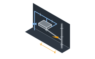
SettingsSettings for this calculationUS
The sum of water supply fixture unit values for every fixture served by this pipe segment.
Add up the WSFU value for each fixture (toilets, sinks, showers, etc.) downstream of this pipe segment, from your local plumbing code's fixture unit table. The IPC and the UPC publish different values for the same fixture — IPC Table E103.3(2) and UPC Table 610.3 — so take them from the code your jurisdiction has adopted rather than from whichever table is nearest to hand.
A calibration constant that scales the square-root approximation to your building's fixture mix.
This constant approximates the shape of the Hunter's curve for a typical fixture mix; adjust it if your building's fixtures (e.g. mostly flush valves vs. mostly tank-type) differ significantly from typical assumptions. Hunter's curve was derived in the 1940s from fixtures that used several times the water modern ones do, and it is well documented as oversizing systems built with low-flow fittings — a lower constant is the honest response where every fixture is low-flow, and it is a judgement rather than a lookup.
The maximum velocity allowed in the pipe to limit noise and water hammer risk.
Around 2.4 m/s (8 ft/s) is a commonly used practical ceiling for domestic water piping — higher velocities increase noise, erosion, and water hammer risk.
The pressure available where the supply enters the building.
Use the utility's stated figure or a gauge reading taken at an outside tap with nothing else running. Mains pressure varies through the day and across the year, and sizing on the best figure you have ever seen produces a system that works at three in the morning. The minimum the supplier guarantees is the number to design against.
The length of pipe from the point of supply to the furthest fixture, following the run.
Measure along the pipe as installed — along the wall, up the riser, across the ceiling void — not the straight-line distance. Fittings are handled separately by the allowance below.
How much extra length is added to represent the elbows, tees and valves in the run.
Every fitting behaves like a length of straight pipe, and on a domestic run the fittings commonly add somewhere between a third and the whole length again. Fifty percent is a working figure for a typical house; a run with many tight bends, several full-bore valves or push-fit inserts that reduce the bore deserves more, and a long straight buried service deserves less.
The height of the highest fixture above the point of supply.
This is pure elevation and it costs about 9.81 kPa (0.433 psi) for every metre climbed, whatever the pipe is made of and however slowly the water moves. A shower head on the second floor of a house is commonly six to seven metres above the service entry, which is around 60 kPa gone before any friction at all.
The pressure the metering assembly loses at your design flow.
Take it from the utility's published curve for the size fitted, at the flow this calculation produces — it rises steeply as the flow approaches the meter's rating, which is why an undersized meter can dominate the whole pressure budget. Include any backflow preventer, strainer or pressure-reducing valve in the same figure; a double-check backflow device alone commonly costs more than the meter.
The flow pressure the furthest fixture needs at its inlet to work properly.
This is flow pressure, measured while the fixture is running, not the static pressure with everything shut. Codes set a minimum for each fixture type and manufacturers state their own; a thermostatic shower valve or a flushometer needs substantially more than a basin tap, and the fixture with the highest requirement on the run is the one to design to.
Which Hazen-Williams roughness coefficient the friction calculation uses.
Smoother pipe loses less pressure over the same run, so material changes the bore the pressure budget demands — though rarely by a whole size. The coefficients here are working values for pipe in service; an old galvanised line that has scaled internally can be far below 120, which is why a system that has always worked starts failing at the top of the house.
Minimum pipe diameter
0.862 in
Velocity governs this run. The diversified demand would fit through a smaller bore on pressure alone, but sustained velocity above the ceiling erodes the pipe and is audible through the building, so the velocity limit is the binding one and the pressure budget has room to spare.
- Estimated peak demand
- 14.31 GPM
- Diameter set by the velocity ceiling
- 0.86 in
- Diameter set by the pressure budget
- 0.77 in
- Pressure lost to static lift
- 58,286.8 Pa
- Pressure lost to friction at this diameter
- 122,120.36 Pa
- Pressure left at the furthest fixture
- 198,803.83 Pa
- Equivalent length used for friction
- 147 ft
They open the calculator with your figures already in it
Domestic Water Pipe Sizing by Fixture Unit Calculator: 0.8616 in — shown in imperial, US market. The link sets both, so the result they see is the one on your screen.
Show calculation logicHide calculation logic
How this was calculated
Formula source(s)
- Estimated demand from fixture units (simplified Hunter's curve approximation) is converted to a minimum pipe diameter via the pipe flow area equation, keeping velocity within a safe range (commonly under ~2.4 m/s / 8 ft/s) to limit noise and water hammer risk
- Hazen-Williams equation (SI units): hf = 10.67 × L × Q^1.852 ÷ (C^1.852 × D^4.8704), used here to find the bore at which friction loss consumes the available pressure
- Static pressure loss = ρgh, at 1000 kg/m³ and 9.80665 m/s² — about 9.81 kPa, or 0.433 psi, per metre of lift
- Water supply fixture unit values are taken from the fixture unit table of the code in force — IPC Table E103.3(2) and UPC Table 610.3 differ, and this page does not reproduce either
Inputs used
- Total Water Supply Fixture Units (WSFU)
- 20
- Demand Factor (Calibration Constant for Your Fixture Mix)
- 3.2
- Maximum velocity
- 7.87 ft/s
- Pressure available at the point of supply
- 60 psi
- Developed length to the furthest fixture
- 98 ft
- Fitting allowance (% added to the length)
- 50
- Height of the highest fixture above the supply
- 19.5 ft
- Pressure lost across the water meter
- 5 psi
- Pressure needed at the furthest fixture
- 15 psi
- Pipe material
- Plastic — PEX, PB, PVC (C = 150)
Intermediate steps
- Estimated peak demand
- 14.31 GPM
- Diameter set by the velocity ceiling
- 0.86 in
- Diameter set by the pressure budget
- 0.77 in
- Pressure lost to static lift
- 58,286.8 Pa
- Pressure lost to friction at this diameter
- 122,120.36 Pa
- Pressure left at the furthest fixture
- 198,803.83 Pa
- Equivalent length used for friction
- 147 ft
Confidence note: Velocity governs this run. The diversified demand would fit through a smaller bore on pressure alone, but sustained velocity above the ceiling erodes the pipe and is audible through the building, so the velocity limit is the binding one and the pressure budget has room to spare.
What this calculation does not cover
- Fixture-unit methods work because fixtures are used intermittently and rarely together. That diversity is the whole basis of the sizing, and it is why the pipe is far smaller than the sum of the fixture flows would suggest.
- Hunter's curve is old, and its age biases this in one direction. It was derived in the 1940s from fixtures using several times the water modern ones do, and it is well documented as oversizing systems built with low-flow fittings — the demand factor is the handle for that, and lowering it is a judgement with consequences rather than a correction.
- Excludes continuous-demand loads such as irrigation and hose bibs, which do not benefit from diversity and are added at their full flow.
- The friction calculation assumes one diameter for the whole run. A real system steps down as branches leave it, so the true loss is somewhere between this figure and the loss of a system sized entirely at the smallest branch — this is the screening answer, and a segment-by-segment calculation is the design one.
- Fitting losses are an allowance, not a count. Each elbow, tee and valve has its own equivalent length and a push-fit insert reduces the bore as well, so the percentage is a stand-in for a takeoff nobody has done. On a run with many tight bends it will understate the loss.
- The meter figure is yours to supply and this page cannot check it. Meter loss rises steeply as flow approaches the meter's rating and a backflow preventer or pressure-reducing valve often costs more than the meter itself; entering a nominal figure where the real assembly loses far more is the quiet way this calculation goes wrong.
- Velocity limits govern independently of flow: sustained velocities above roughly 2.4 m/s (8 ft/s) cause erosion and noise regardless of what the fixture units allow.
- The result is an internal diameter, not a pipe size. Nominal designations are not bores — copper, PEX and CPVC of the same nominal size have materially different internal diameters, and a push-fit system loses more at every joint — so take the next size up whose actual bore meets this figure in the material you are using.
Add the equipment this sizes
This result is a specification — 0.862 in — not a quantity. Put the thing it sizes into your project: how many, what you call it, and your supplier’s price.
Computed in your browser — nothing you enter is uploaded. Presented in US customary units and US trade terminology. Where a formula follows a published standard, that standard and its edition are cited beside it on this page; where none governs, the page says so. Local amendments override model codes — verify against the code in force where you build.
Sources checked 2026-09-11 · v1.1.0
Regulatory standards & verification citations4
- Estimated demand from fixture units (simplified Hunter's curve approximation) is converted to a minimum pipe diameter via the pipe flow area equation, keeping velocity within a safe range (commonly under ~2.4 m/s / 8 ft/s) to limit noise and water hammer risk
- Hazen-Williams equation (SI units): hf = 10.67 × L × Q^1.852 ÷ (C^1.852 × D^4.8704), used here to find the bore at which friction loss consumes the available pressure
- Static pressure loss = ρgh, at 1000 kg/m³ and 9.80665 m/s² — about 9.81 kPa, or 0.433 psi, per metre of lift
- Water supply fixture unit values are taken from the fixture unit table of the code in force — IPC Table E103.3(2) and UPC Table 610.3 differ, and this page does not reproduce either
Which documents these citations point at
- International Plumbing Code — Table E103.3(2) (United States)Plumbing systems — fixtures, water supply, sanitary drainage, venting and storm drainage.
- Uniform Plumbing Code — Table 610.3 (United States)Plumbing systems, where a jurisdiction adopts the IAPMO family rather than the ICC one. Its fixture-unit tables differ from the IPC's.
A code or standard has force only where a jurisdiction has adopted it, usually with local amendments. This site holds no adoption data for any authority, so check what is in force with the authority where you build. Any section cited above without an edition should be checked against the edition in force where you build. What it would take to know.
Cite this page
Your workspace
Most jobs need more than one number. Add the calculators you need next and they open right here, underneath this one — your figures stay on screen and nothing is lost to a page change.