
SettingsSettings for this calculationUS
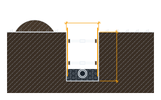
The width of the roadway (or embankment) the culvert must span underneath.
Measure the full width the pipe must cross, including shoulders if the culvert extends beneath them.
The extra pipe length needed at each end for a headwall or end section.
This length lets the pipe extend beyond the roadway width so a headwall, flared end section, or apron can be attached.
Culvert pipe length needed
49 ft
They open the calculator with your figures already in it
Culvert Pipe Length Calculator: 49 ft — shown in imperial, US market. The link sets both, so the result they see is the one on your screen.
Show calculation logicHide calculation logic
How this was calculated
Formula source(s)
- Total pipe length = roadway width + 2 × end treatment length, accounting for the pipe extending beyond the roadway width to accommodate headwalls or end sections at each end
Inputs used
- Roadway Width to Span
- 39 ft
- End Treatment Length (Each End)
- 5 ft
What this calculation does not cover
- The result spans only the width you type in. It adds nothing for the pipe running out under the embankment side slopes, and under any fill that is the largest term in the length: the barrel crosses at invert level, where the embankment is wider than the road surface by roughly twice the fill height times the side-slope run. Enter the embankment width at the pipe's own elevation, not the width of the pavement.
- The crossing is treated as square to the roadway. A culvert skewed to the centreline is longer than the perpendicular span by a factor of 1 over the cosine of the skew angle, and none of that is included here.
- The answer is a horizontal straight-line span. A barrel laid on grade is slightly longer than its horizontal projection, and pipe is supplied in fixed section lengths, so the figure has to be rounded up to whole sections and the joint laps added before anything is ordered.
- This is a length take-off, not a culvert design. It says nothing about the pipe diameter needed, whether the culvert passes the design storm, the minimum and maximum cover over the crown, bedding, or the pipe class or gauge required for the fill height and traffic loading. Those come from a hydraulic analysis and the pipe supplier's and reviewing agency's cover tables.
- The end treatment allowance is taken exactly as you enter it. Nothing checks it against the actual flared end section, headwall, wingwall, apron or bevelled end being built, or against what the reviewing agency requires, and no allowance is made for cutoff walls or aprons beyond the pipe itself.
Estimated cost — your price
This site holds no price list for this material — local prices vary too much to publish honestly. Enter your supplier's price and the result is costed with it.
Computed in your browser — nothing you enter is uploaded. Presented in US customary units and US trade terminology. Where a formula follows a published standard, that standard and its edition are cited beside it on this page; where none governs, the page says so. Local amendments override model codes — verify against the code in force where you build.
Sources checked 2026-09-02 · in the site-wide review of 2026-09-06 · v1.0.1
Regulatory standards & verification citations1
- Total pipe length = roadway width + 2 × end treatment length, accounting for the pipe extending beyond the roadway width to accommodate headwalls or end sections at each end
Cite this page
Your workspace
Most jobs need more than one number. Add the calculators you need next and they open right here, underneath this one — your figures stay on screen and nothing is lost to a page change.