
SettingsSettings for this calculationUS
Accounts for the additional deflection that develops over time under sustained load.
Spangler introduced it because a pipe keeps deflecting after the backfill is placed, as the soil at the sides consolidates and takes up its share of the load. 1.0 gives the deflection at the moment of installation; values up to about 1.5 cover the long term, and which end to use depends on how well the sidefill was compacted — a well-compacted haunch reaches its final state quickly, a poorly compacted one keeps moving for years. Design against the long-term value; check the installation against the immediate one.
Depends on the bedding angle supporting the pipe.
It describes how far around the invert the pipe is actually supported. A pipe laid on a flat trench bottom bears on a narrow strip and takes the highest value; one bedded into shaped granular material over a wide angle spreads the reaction and takes a lower one. The range is narrow — roughly 0.11 down to 0.08 across the practical bedding angles — but it is the one term on this page that is decided entirely by workmanship on the day, and it is the first thing to question when a pipe deflects more than the calculation said.
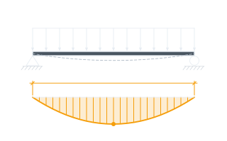
The soil cover (and any surcharge) load transmitted to the pipe, per unit of pipe length.
For a flexible pipe in a properly compacted embankment the prism load — the weight of the soil column directly above the pipe — is the usual basis, because a flexible pipe deflects and sheds load to the sidefill rather than attracting it. A rigid pipe in a narrow trench behaves differently and Marston's trench theory applies instead. Live load from traffic is added on top and matters most at shallow cover, where it can exceed the soil load entirely.
The pipe's mean wall radius.
MEAN radius — to the middle of the wall, not the inside or the outside face. The formula carries r³, so the error compounds: taking the outside radius on a thick-walled pipe overstates deflection noticeably, and on a large-diameter pipe the difference between inside and mean is not small. Half the mean diameter is the quickest way to it.
The pipe wall's stiffness per unit length (modulus of elasticity × moment of inertia).
EI per unit length of pipe, which is NOT the pipe stiffness a parallel-plate test reports. Test results are usually quoted as PS, the load per unit deflection at 5%, and the two are related through the mean radius — so a figure taken off a test certificate has to be converted before it belongs here. Entering PS where EI is wanted is the commonest error on this calculation, and it is out by orders of magnitude rather than by a margin anyone would notice as a slip.
Reflects the stiffness of the compacted soil embedment surrounding the pipe.
AASHTO tabulates E' by backfill type and compaction, commonly 7 MPa (about 1,000 psi) for well-compacted granular embedment.
Calculated pipe deflection
0.48 in
The deflection the Iowa formula gives this pipe is below 5% of the diameter shown with it — AASHTO's conventional limit gives it. Being under the allowable pressure is not the whole ground question: settlement, groundwater and the footings alongside are all untouched here.
- Allowable deflection (5% of diameter, AASHTO)
- 1.18 in
They open the calculator with your figures already in it
Flexible Culvert Pipe Deflection Calculator (Iowa/Modified Spangler Formula): 0.4801 in — shown in imperial, US market. The link sets both, so the result they see is the one on your screen.
Show calculation logicHide calculation logic
How this was calculated
Formula source(s)
- Modified Iowa Formula (Spangler 1941, Watkins & Spangler 1958): Δx = (Dl×K×W×r³)/(E×I + 0.061×E'×r³), where Dl is the deflection lag factor (typically 1.0-1.5), K is the bedding constant (typically ~0.10 for standard bedding), W is the load per unit pipe length, r is the mean pipe radius, EI is the pipe wall stiffness per unit length, and E' is the modulus of soil reaction — a well-established formula per AASHTO LRFD and state DOT culvert design manuals
Inputs used
- Deflection Lag Factor (Dl, Typically 1.0-1.5)
- 1.5
- Bedding Constant (K, Typically ~0.10)
- 0.1
- Load per Unit Pipe Length (N/mm)
- 50
- Mean Pipe Radius
- 11.75 in
- Pipe Wall Stiffness EI (N·mm²/mm)
- 5000000
- Modulus of Soil Reaction E'
- 1015.26 psi
Intermediate steps
- Allowable deflection (5% of diameter, AASHTO)
- 1.18 in
Confidence note: The deflection the Iowa formula gives this pipe is below 5% of the diameter shown with it — AASHTO's conventional limit gives it. Being under the allowable pressure is not the whole ground question: settlement, groundwater and the footings alongside are all untouched here.
What this calculation does not cover
- The load figure is whatever you type in — this calculation does not build it. It does not work out the soil prism load from cover depth and pipe width, does not add wheel or construction-plant live load, and does not distribute a live load down through the cover. At shallow cover the traffic load can exceed the soil load entirely, and it is on you to derive it and include it before entering a figure.
- This checks one limit state and nothing else. Wall thrust and crushing, wall buckling in weak embedment, seam and joint capacity, longitudinal bending over a soft spot, flotation of an empty pipe, and hydraulic capacity all sit outside it — a pipe can come in under the 5% screen and still fail on any of them. It is a screening check, not a culvert design, and it does not replace the deflection limit your pipe manufacturer or road authority sets.
- E', the bedding constant and the lag factor are assumptions about how the pipe will be bedded and backfilled, and the calculation treats them as achieved. Nothing here verifies compaction. Only a deflection test after the backfill is placed — mandrel or laser profile — tells you what the installation actually delivered, and that test is what governs acceptance.
- Flexible pipe only. It does not describe concrete, clay or other rigid pipe, which attracts load into the barrel rather than shedding it to the sidefill and needs a crushing-strength check instead. Entering rigid-pipe properties here returns a number that means nothing.
- The wall stiffness is treated as a single fixed value. Thermoplastic pipe loses stiffness over its service life and stiffens in cold weather, and the deflection lag factor covers the soil's continued consolidation, not the pipe material's own creep. A long-term check needs a long-term EI, which is not what a short-term parallel-plate test certificate gives you.
Add the equipment this sizes
This result is a specification — 0.48 in — not a quantity. Put the thing it sizes into your project: how many, what you call it, and your supplier’s price.
Computed in your browser — nothing you enter is uploaded. Presented in US customary units and US trade terminology. Where a formula follows a published standard, that standard and its edition are cited beside it on this page; where none governs, the page says so. Local amendments override model codes — verify against the code in force where you build.
Sources checked 2026-09-02 · in the site-wide review of 2026-09-06 · v1.0.1
Regulatory standards & verification citations1
- Modified Iowa Formula (Spangler 1941, Watkins & Spangler 1958): Δx = (Dl×K×W×r³)/(E×I + 0.061×E'×r³), where Dl is the deflection lag factor (typically 1.0-1.5), K is the bedding constant (typically ~0.10 for standard bedding), W is the load per unit pipe length, r is the mean pipe radius, EI is the pipe wall stiffness per unit length, and E' is the modulus of soil reaction — a well-established formula per AASHTO LRFD and state DOT culvert design manuals
Cite this page
Your workspace
Most jobs need more than one number. Add the calculators you need next and they open right here, underneath this one — your figures stay on screen and nothing is lost to a page change.