
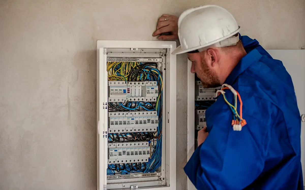
Chalk, Then Concrete
The studs are up, the plumber has been through, and somebody has written a boarding date on the programme. From this morning until that date the wall is an open book, and after it every decision you make today is behind twelve millimetres of gypsum and a coat of paint. That asymmetry is the whole character of first fix. Nothing you mark is hard work; everything you fail to mark is a chase, a patch, a repaint, and an argument about who pays for it.
Two kinds of decision get made in the same hour and they are worth separating. One is forced: a count and a maximum spacing a code has already settled and an inspector will check with a tape. The other is nobody's rule and everybody's complaint — the socket behind the bed head, the switch on the hinge side of a door that swings the other way, the desk outlet four hundred millimetres short. The first kind stops the job failing. The second is the difference between a compliant house and one somebody likes living in.
The forced ones also split by surface. Receptacles are a wall exercise, driven by lengths measured along the floor line. Alarms are a ceiling exercise, driven by rooms, storeys and what else is fixed to that ceiling, and their cabling has to be in before the ceiling closes rather than before the walls do. Work the wall and the ceiling as two separate passes, because a single pass around a room mixes horizontal and vertical rules and drops one of them.
Six Feet, Measured the Way the Code Measures It
The general spacing rule for a dwelling sits in NFPA 70 National Electrical Code 210.52, and it is stated as a reach rather than as a pitch: no point measured horizontally along the floor line of any wall space may be more than 6 ft from a receptacle outlet. Twelve feet between outlets is the consequence, not the rule, and the difference matters at the ends of a run. A wall space that begins at a door casing needs a receptacle within 6 ft of that casing, so a socket that sits a comfortable 12 ft from its neighbour can still leave the first stretch of wall non-compliant. What the clause is really protecting against is the extension lead a householder buys when nothing reaches, and the reason it is written in feet of reach is that a lamp flex is about six of them.
Then read the definition of wall space, which is where most counts go wrong. It is any space 2 ft or more in width, measured around corners, unbroken along the floor line by doorways, fireplaces and similar openings; it includes the space occupied by fixed panels in walls, with the treatment of sliding panels having been reworded between editions; and it includes the space afforded by fixed room dividers such as railings and freestanding bar-type counters. A room is therefore not one perimeter. It is a set of wall spaces, some of them a metre long, each of which has to satisfy the reach on its own account.
Practically, that means a corner does not break a run and you carry the measurement around it, while a doorway does break it, and the short return between a door casing and the corner is its own wall space the moment it reaches two feet. Kitchen and bedroom layouts are full of those returns. A floor receptacle only counts towards the wall it serves if it sits within 18 in of that wall, which rules out the box you were going to put under the middle of the dining table. And a receptacle installed to satisfy the rule has to be a receptacle you can plug into, not one behind a fitted wardrobe carcass.
Whatever number falls out of the arithmetic is a floor. Build to the minimum and you have designed a room where every socket is in use and none is where anybody wants it. Add positions for the bed heads, the desk, the television wall and the vacuum point, and note that some of those positions dictate the device rather than the box: where ground-fault or arc-fault protection is provided at the receptacle instead of at the breaker, the first box on the run is the one that has to be big enough and reachable enough to hold it. Tamper-resistant receptacles are required in dwellings under Article 406, which is a purchasing decision made at the same desk as this one.
Feed it one wall space at a time — the run between two doorways, then the return beside the casing — rather than the room perimeter, because the reach rule is applied to each of those separately and a perimeter figure hides the short ones. It never answers below two, so on any space shorter than 12 ft read that two as one position and satisfy the 6 ft reach from the ends of the space yourself.
The length of one continuous wall space, not the whole room.
Minimum outlets for this wall space
4 outlets (minimum)
- Wall run length
- 39 ft
They open the calculator with your figures already in it
Outlet Spacing Calculator: 4 outlets (minimum) — shown in imperial, US market. The link sets both, so the result they see is the one on your screen.
Estimated cost — your price
This site holds no price list for this material — local prices vary too much to publish honestly. Enter your supplier's price and the result is costed with it.
What this calculation does not cover
- This counts receptacles for reach spacing only. It is not a load calculation: it says nothing about how many outlets a branch circuit may carry, what conductor size or breaker the run needs, or where GFCI, AFCI or tamper-resistant devices are required.
- The count applies to one continuous wall space. Doorways, fireplaces and sliding or opening floor-length panels end a wall space and begin a new one (a fixed panel counts as wall space under NEC 210.52(A)(2)), and each new space carries the reach requirement on its own account, so a room's total wall length run through this in one go can return fewer outlets than the code needs — up to one short for every extra space. Run each space on its own and add the counts.
- Special locations sit outside this rule entirely. Countertops, bathroom basins, hallways, garages, outdoor walls and laundry areas are governed by their own tighter reach distances or by a flat count, and the island and peninsula provisions have been rewritten between recent NEC editions.
- The number assumes every receptacle counts toward the rule and can be placed wherever the arithmetic wants it. Outlets mounted high on the wall, inside a cabinet, behind a fitted wardrobe carcass, or set in the floor away from the wall it serves may not count toward the spacing requirement, and none of that is modelled.
- This is the North American reach rule and nothing else. BS 7671 sets no socket-outlet spacing requirement in a UK dwelling, and even in the US the adopted NEC edition and any local amendment govern — the result is a code-minimum starting count for a licensed electrician to check, not a layout or a plan.
Where That Rule Stops Applying
The general spacing rule is the residential default, and it stops at the doorway of about half the rooms in a house. Counter spaces work to a tighter reach and to a maximum height above the worktop; a bathroom wants a receptacle within a stated distance of each basin; a hallway earns one only once it reaches a length the code names; garages, outdoor walls and the laundry each carry a count rather than a spacing. Island and peninsula provisions were rewritten in both the 2020 and 2023 editions of NFPA 70, so the rule you applied on your last job may genuinely no longer be the rule. Read the edition your authority having jurisdiction has adopted, together with any local amendment, rather than the version you learned.
Step outside North America and the framework changes shape entirely. BS 7671 Requirements for Electrical Installations contains no spacing clause for socket-outlets at all — how many go in a UK living room is a design decision agreed with the client, not a number an inspector measures with a tape. What BS 7671 does impose is protection: residual current protection for socket-outlets, restrictions on where concealed cables may run, and the arc fault detection requirements introduced by Amendment 2 for specified premises. Position, meanwhile, comes from Approved Document M, which fixes the height band in a new dwelling. A UK first fix is therefore governed by heights, cable zones and protective devices; a US one is governed by reach. Neither set of habits transfers.
| Location | What governs it | The mark that gets missed |
|---|---|---|
| Habitable room wall | NFPA 70 210.52 reach along the floor line | The short return between door casing and corner |
| Kitchen counter | Its own tighter reach plus a maximum height above the worktop | An appliance garage or splashback that swallows the position |
| Island or peninsula | Provisions rewritten in recent NEC editions — read the adopted one | A face-up position that the current edition no longer allows |
| Bathroom | A stated distance from the outside edge of each basin | The basin moving 200 mm at second fix |
| Hallway | A count once the hallway reaches the length the code names | Measured after the alarm position, so both end up in the same joist bay |
| Garage and outdoors | A count per vehicle bay and at the front and rear walls | The bay outlet buried behind stored shelving |
| UK dwelling generally | No spacing rule in BS 7671; height band from Approved Document M | Assuming the North American 12 ft pitch applies |
Heights Nobody Writes on the Drawing
NFPA 70 sets no general mounting height for a receptacle in a dwelling, only a ceiling on which ones count: a receptacle more than 5-1/2 ft above the floor is excluded from satisfying the 210.52 spacing, and so is one inside a cabinet or cupboard. Below that line habit sets the height, and habit is remarkably consistent — a hand span off the floor to the bottom of the box, a switch at door-handle reach — which is why nobody writes it down and why a crew that changes halfway through a house leaves a visible step in a line of sockets. Where accessibility provisions apply, the height stops being habit: ICC A117.1 Accessible and Usable Buildings and Facilities puts operable parts inside a reach range measured from the floor, and Approved Document M volume 1 sets the band for switches and socket outlets in a new UK dwelling at 450 mm to 1200 mm above finished floor level. Both of those are measured to the finished floor, which is a surface that does not yet exist.
So strike a datum and work from it. A line pulled around the room at a metre, or at four feet, gives every box in the room the same reference regardless of what the floor is doing, and it survives the screeder. Working off the subfloor instead costs you the whole build-up — twenty millimetres of tile on thirty of screed is fifty millimetres of error that only becomes visible when the sockets in the tiled room sit lower than the ones in the hall next to it. Mark the datum, mark the box centres off it, and leave the line on the studs for the inspector and for yourself.
The heights that cause real trouble are the ones another trade owns. A socket over a worktop is fixed by the worktop height and by a maximum dimension above it. A box behind an appliance is fixed by the appliance depth and by whether its door will open across the plug. A television position is fixed by a bracket that has not been bought. Get the joinery drawing, the appliance schedule and the sanitaryware sheet in front of you before the boxes go on, and where those documents do not exist yet, put the box where the code forces it and add a second position for the thing you cannot yet dimension. A spare box behind a plate is cheap; a chase in a tiled wall is not.
Getting the Cable There Without Weakening the Wall
Cable reaches the box through the frame, and the frame has structural rules that are older than the circuit. IRC R602.6 governs drilling and notching of studs: notches are limited to 25 percent of the stud width in an exterior wall or bearing partition and 40 percent in a non-bearing partition. Bored holes are held to 40 percent of the stud width in an exterior wall or bearing partition, rising to 60 percent there only where the stud is doubled and no more than two doubled studs run in succession, while a non-bearing partition takes 60 percent on a single stud — which is why the wall's role has to be settled before the drill comes out, not after. The hole edge is kept back from the stud edge by the dimension the section names. Engineered and finger-jointed studs come out of that table entirely and are governed by the manufacturer's evaluation report. Bore, do not notch, wherever there is a choice: a notch removes material from the face that is working hardest and turns the stud into a hinge, while a centred bore leaves the section symmetric.
The electrical half of the same detail is NFPA 70 300.4(A), cables and raceways through wood members: its bored-hole clause requires that where the edge of a hole finishes less than 1-1/4 in from the nearest edge of the wood member, a steel plate at least 1/16 in thick protects it, and the notching clause immediately after it protects a notched member the same way. That plate is not for the cable's benefit alone. It is for the drywall screw, the picture hook and the shelf fixing that arrive in that wall over the next thirty years. Support follows: sheathed cable is secured within a stated distance of every box and at intervals along the run, and a cable left swinging in a bay will be found by the insulation crew and dragged out of the box. Drill a straight, consistent line of holes at one height across the room and the next trade can predict where your cable is; scatter them and somebody will find one with a screw.
In the UK the constraint is geometric rather than percentage-based. BS 7671 confines concealed cables to prescribed zones — a band near the top of the wall, a band at an internal corner, and the vertical and horizontal bands running from an accessory — and a cable buried less than 50 mm from the surface has to be in such a zone with 30 mA residual current protection, or else carry an earthed metallic covering or mechanical protection. Metal stud framing changes the problem again: every knockout takes a bush or a grommet, because a 0.5 mm steel web edge will cut a cable jacket given a decade of thermal movement, and boxes want a fixing channel or a proprietary bracket rather than a pair of screws into one thin web.
Put the stud size and the wall's role into it before the first hole, since the answer decides whether you are boring, boring and plating, or doubling the stud — and all three are cheap now and expensive after the boards.
The dressed depth of the stud — the dimension the drill passes across.
Whether the wall carries load from above, or only its own weight and finishes.
Whether the stud being drilled has been doubled up to carry a larger hole.
Whether the service passes through a drilled hole or sits in an edge notch.
The size you intend to cut — the hole's diameter, or the depth of the notch.
Maximum permitted bore or notch
1.4 in
The planned cut is within the 1.40 in the code allows for this stud. Enough wood remains between the service and the face that no protection plate is required, though many inspectors expect one anyway where a fastener could plausibly find the pipe. A bored hole and a notch may not share the same section of stud.
- Largest bore this stud allows
- 1.4 in
- Deepest notch this stud allows
- 0.88 in
- Cover left to the nearest face
- 1.32 in
- Minimum clearance to the stud edge
- 0.63 in
They open the calculator with your figures already in it
Stud Boring and Notching Limit Calculator: 1.4 in — shown in imperial, US market. The link sets both, so the result they see is the one on your screen.
Add the equipment this sizes
This result is a specification — 1.4 in — not a quantity. Put the thing it sizes into your project: how many, what you call it, and your supplier’s price.
What this calculation does not cover
- Sawn lumber studs only. Engineered, finger-jointed and cold-formed steel studs are governed by their own evaluation reports, which usually permit larger holes in defined positions and no notching at all.
- Does not check shear walls or braced wall panels, where sheathing nailing and hold-downs impose their own restrictions on what may be cut.
A Box Front Has to Finish Flush With a Surface That Is Not There Yet
Hanging a box off the stud face is the easy part, and it is the wrong reference. NFPA 70 314.20 sets the box against the finished surface, not the framing: in a wall or ceiling with a noncombustible surface material the box front may be set back no more than 1/4 in, and where the surface material is combustible the box has to be flush with it or project from it. The companion clause, 314.21, deals with the aftermath — gaps and open spaces at the edge of the opening greater than 1/8 in have to be made good — which is the code telling you, politely, that a box hung too deep becomes the boarder's problem and then the decorator's.
The moulded depth gauge on a nail-on box assumes one board thickness, and half the walls in a modern house are not that thickness. Fire-rated board, a double layer in a separating wall, a skim coat, ten millimetres of tile and its adhesive, or a wall being battened out for services each move the finished plane forward. That is what a mounting ring is for, and rings are sold in a ladder of depths precisely so a box can be hung once and referenced to any of those surfaces. Fitting the right ring at first fix costs a few pence. Fitting a box extender at second fix costs a visit, and looks like one.
While the box is still a choice rather than a fixture, settle the volume as well as the depth. Box fill under NFPA 70 314.16 counts conductors, devices, clamps and grounding conductors, and a three-gang plate holding two dimmers and a run of travellers eats a single-gang assumption alive. The box you can still swap this morning is a shallow one; the box you cannot swap is the one behind a taped and skimmed wall with a device that will not fold back into it. Ceilings carry the same logic in a different clause — a box that will support a ceiling-suspended fan has to be listed and marked for that duty, and that is a decision made before the ceiling closes, not when the fan arrives in a carton.
The last dimension is horizontal, and it belongs to the drywaller rather than to you. A box that lands on a sheet joint turns a straight cut into a jigsaw of two half-openings that never quite line up behind the plate. Shift the box a stud bay, or shift it far enough along the same bay that the opening sits clear of the joint, and the plate sits flat on one board.
What closes over a device box
- Cover plate and device — the only part anyone ever sees, and the part that reveals a box hung to the wrong reference by sitting proud or sunk
- Finish board — sets the plane the box front is measured against, and its thickness is what the box depth gauge assumed rather than what the wall got Drywall Calculator
- Air and vapour control layer — continuous until a box interrupts it, which is why an airtight enclosure or a sealed collar is a first-fix item and not a snagging one Vapor Barrier Calculator
- Device box and mounting ring — hung to the finished surface rather than the stud face, with the ring depth chosen for the board, skim and tile that follow Outlet Spacing Calculator
- Bored stud and cable run — the hole size and its distance from the stud edge decide whether a steel protection plate is required over it Stud Boring and Notching Limit Calculator
Boxes in a Wall That Has to Hold Fire, or Hold Sound
In a fire-resistance-rated partition every box opening is a membrane penetration, and the wall's rating came from a tested assembly under ASTM E119 Standard Test Methods for Fire Tests of Building Construction and Materials or UL 263, in which nobody cut a row of holes. The International Building Code accordingly caps what you may cut: steel electrical boxes whose individual face area does not exceed 16 in², with the aggregate area of such openings limited to 100 in² in any 100 ft² of wall area. Boxes on opposite faces of the same wall are separated by a horizontal distance of not less than 24 in unless they are separated by the insulation the code describes, by solid fireblocking, or protected by a listed putty pad or other listed material.
Those two limits bite in different places. The 24 in separation catches the domestic case — the socket in the bedroom that a lazy layout puts directly behind the socket in the landing, sharing one stud bay and one straight path through the wall. The aggregate cap catches the commercial case, where a corridor wall picks up switches, sockets, a card reader and a fire alarm call point on both faces and the arithmetic quietly runs out of allowance. Neither is obvious from a plan. Both are trivial to check while the boxes are chalk marks.
The same offset earns its keep acoustically, for reasons that have nothing to do with fire. Back-to-back boxes short-circuit a separating wall's performance by removing board from both leaves at the same point and handing airborne sound a direct route through the cavity. Offsetting by at least one bay and packing the box with a listed putty pad answers both problems with one product, and putty pads are one of the few materials on a job that a fire consultant and an acoustician will both sign off without argument.
Count the boxes on both faces of a rated wall and put them through the cap before anything is fixed, because the fix for an over-populated partition is relocating boxes, and that is a different job once cable has been run to them.
The rating of the assembly the boxes are being cut into. The box allowance stops at 2 hours.
The opening one box cuts through the board, not the volume of the box.
How many boxes are set into the area of wall you entered below.
The area of rated wall the boxes above are distributed across.
The closest horizontal offset between a box on one side and a box on the other.
Whether a listed protection method is used in place of the separation distance.
Aggregate box area against the cap
96 % of the cap
The layout is inside the code's limits for opening area, box size and separation. That is a check on the openings, not a verification of the wall's rating, which comes from the tested assembly it was built to.
- Aggregate box opening area
- 0.67 ft²
- Cap for the wall area entered
- 0.69 ft²
- Boxes this wall area can carry at that size
- 6 boxes
- Largest single box allowed without a listed system
- 0.11 ft²
- Separation required between opposing boxes
- 24 in
- Separation entered
- 24 in
They open the calculator with your figures already in it
Firestop Membrane Penetration Box Area Calculator: 96 % of the cap — shown in imperial, US market. The link sets both, so the result they see is the one on your screen.
Add the equipment this sizes
This result is a specification — 96 % of the cap — not a quantity. Put the thing it sizes into your project: how many, what you call it, and your supplier’s price.
What this calculation does not cover
- Steel boxes only. Non-metallic boxes are permitted solely where they are part of a listed assembly, with their own conditions.
- The rating of the wall itself is not verified here; the assembly's own listing governs. Above 2 hours the prescriptive allowance does not apply at all, and this page says so rather than scoring the layout.
- Local amendments to the adopted code are common on this provision and are not applied.
- Larger openings, sleeves and through penetrations follow different provisions entirely.
On aggregate area: 96% of the prescriptive cap, so this patch of wall is inside it at up to 6 boxes of the size entered. On separation: the boxes on opposite faces are at or beyond the 24 in (610 mm) the provision states.
Alarms Are a Ceiling Plan, and They Are Not Yours to Guess
The count comes first because it drives the cable, and it comes from a code rather than from experience. IRC R314 puts a smoke alarm in each sleeping room, one outside each separate sleeping area in the immediate vicinity of the bedrooms, and one on each additional storey including basements and habitable attics, interconnected so that one sounding sounds them all. Scotland's Building Standards Technical Handbook reaches a similar place by a different route: an alarm in the room most used for daytime living, one in every circulation space on each storey, a heat alarm in the kitchen, all interlinked. In England and Wales, Approved Document B points at BS 5839-6, which describes domestic systems by grade — what the equipment is and how it is powered — and by category, meaning how much of the house is covered. Which grade and category apply is a question for the standard and the building control officer together, settled before you buy heads.
A count is not a plan, though, and NFPA 72 National Fire Alarm and Signaling Code owns the difference. Alarms are kept clear of the supply register of a forced-air system and of the tip of a paddle fan blade by a stated horizontal distance, because moving air thins smoke before it reaches the sensing chamber. They are kept back from a stationary cooking appliance by a distance that relaxes where a photoelectric alarm is used, and an alarm sited within a stated radius of cooking has to be photoelectric or carry a silencing means. IRC R314 separately keeps them clear of the door of a bathroom containing a bathtub or shower. Every one of those exclusions exists because a nuisance alarm gets twisted off its base, and a house with a disabled alarm is worse protected than the count on the order sheet suggests.
Ceiling geometry decides the rest. On a sloped or cathedral ceiling the alarm belongs near the peak, within a stated horizontal distance of it but not in the very top few inches, because the apex itself holds a pocket of still air. A wall-mounted alarm sits in a band below the ceiling rather than anywhere on the wall. The corner dead-air-space rule that older training insisted on for ceiling mounting has been relaxed in recent NFPA 72 editions, but the manufacturer's printed instructions still govern the installation and plenty of them still carry it, so read the leaflet in the box you actually bought. Room size matters too: NFPA 72 works from a nominal spacing on a smooth, level ceiling, which means one alarm satisfies the outside-the-bedrooms requirement in a short landing and does not satisfy anything much on a long corridor or an open-plan ground floor.
What all of that costs you at first fix is cable and blocking. Interconnection runs through the ceiling void, so it goes in before the ceiling closes, and a radio-interlinked head still needs a permanent supply at each base — the radio replaces the interconnect conductor, not the circuit. Fix every base to a noggin or a hanger rather than to the board, and keep the alarm position off the line of a recessed downlight, a hatch or a fan before the ceiling grid is set out. Chasing an interlink into a finished, taped and skimmed ceiling means cutting open the surface you have just paid to install, and where that ceiling is also a fire-resisting one, a repaired penetration is only as good as the person who repaired it.
Take the bedrooms and storeys through it to get an ordering figure for the wholesaler while the ceiling is still open — a number to buy against, not a placement design, which comes from the standard and the manufacturer's instructions.
Each bedroom needs its own detector.
Each level of the home needs at least one detector, including a basement whether or not it is finished.
Smoke detectors needed
6 detectors (minimum)
This is a simplified rough minimum, not a code compliance check. NFPA 72 and your local building code have specific, more detailed placement rules (including for hallways, large bedrooms, and rooms with sloped ceilings) — always verify against your local fire code and manufacturer instructions, and consider interconnected detectors so all units sound together.
They open the calculator with your figures already in it
Smoke Detector Placement Calculator: 6 detectors (minimum) — shown in imperial, US market. The link sets both, so the result they see is the one on your screen.
Estimated cost — your price
This site holds no price list for this material — local prices vary too much to publish honestly. Enter your supplier's price and the result is costed with it.
What this calculation does not cover
- Floor area never enters the arithmetic. A 40 m² (431 ft²) storey and a 200 m² (2,153 ft²) open-plan one both get a single alarm, but NFPA 72 and local codes limit how far an alarm can be from the space it protects, so a long hallway, a large open level, or a floor split into separated wings needs more than the one per level this count allows.
- Only one alarm is added outside the sleeping areas, whatever the plan. The calculation cannot see how the bedrooms are grouped, so a home whose bedrooms sit in several separate clusters has to have the total raised by hand.
- This is a device count, not electrical design and not a load calculation. It does not size or check the circuit the alarms sit on, count the interconnect conductors between them, or choose between mains-wired units with battery backup and sealed ten-year battery units — and which of those is permitted usually turns on whether the work is new build or a retrofit.
- Smoke alarms only. Carbon monoxide alarms, a heat alarm in a garage or loft, and detection for anything beyond a single-family home — flats with shared escape routes, houses in multiple occupation, commercial premises — are separate requirements designed to a detection standard, not counted from bedrooms and floors.
- Nothing here accounts for what is already on the ceiling. Alarms carry a service life printed on the unit and are commonly retired ten years from the date of manufacture, so existing units offset this total only if they are in date and of a type your code still accepts.
Carbon Monoxide Follows the Fuel
Carbon monoxide detection is a separate requirement with a separate trigger, and mapping it onto the smoke alarm plan is the standard mistake. IRC R315 places carbon monoxide alarms outside each separate sleeping area in the immediate vicinity of the bedrooms, in dwelling units containing fuel-fired appliances, and in dwelling units with an attached garage. The provisions once carried by NFPA 720 now live in NFPA 72. Approved Document J requires an alarm in the same room as a solid fuel appliance, Scotland's Building Standards Technical Handbook requires one wherever there is a carbon-fuelled appliance, and the alarms themselves are specified to BS EN 50291 with selection and siting guidance in BS EN 50292.
Height is the part that reads oddly to anyone used to smoke alarms. Carbon monoxide mixes with air rather than rising as a hot plume, so the UK guidance permits a ceiling mount at least 300 mm from any wall, or a wall mount above the height of any door or window but at least 150 mm below the ceiling, in both cases between one and three metres horizontally from the appliance. Follow the manufacturer's instructions, which are the governing document for the specific alarm. And walk the fuel rather than the bedrooms when you site them: the boiler in the airing cupboard, the flue that passes through the corner of a bedroom on its way to the ridge, the room over an integral garage. Those are the positions a plan drawn from the sleeping areas alone will miss.
Mark It, Then Prove It
Marking is a sequence, and doing it in the wrong order is why boxes get moved twice. Settle the datum first, then the forced positions, then the ones the occupant will care about, then the framing work needed to reach any of them. Only once all of that is on the studs does anything get screwed down, because the third box is usually the one that shows the first two were 100 mm out.
Then prove it before anybody covers it up. Photograph every wall with a tape in shot and a marker board naming the room, walk the ceiling positions against the alarm plan rather than against memory, and check the marked heights off the datum one last time. Those photographs are what settles where the cable runs when a shelf goes up in three years, and they take a fraction of the time that finding a buried cable with a detector does.
- Strike a datum around the room at a metre or four feet and leave it on the studs.
- Break the room into wall spaces at the doorways and openings, then apply the reach rule to each one separately.
- Add the positions the code does not force: bed heads, desk, television wall, and anything the joinery drawing implies.
- Set switch positions against the door swing shown on the plan, not the swing the door is currently hung on.
- Check both faces of any rated or separating wall for back-to-back boxes and offset them before fixing.
- Choose ring depth per wall from the finish schedule, not from the box's moulded gauge.
- Bore the frame in one consistent line, plate anything closer to the edge than the code allows, and support the cable back to each box.
- Mark alarm positions clear of registers, fans, downlights and hatches, and fix a noggin at each one.
Turning the marks into an order
Work the wall first and the ceiling second, and settle every quantity that depends on the finish — ring depth, box volume, plate count — while the frame is still open enough to change your mind.
- Boxes and mounting rings, counted per wall space — Count against the reach rule applied to each wall space in turn, then add the positions the occupant will want; ring depth is chosen per room from the finish schedule.
- Protection plates and cable supports — One plate for every bore or notch that finishes closer to the framing edge than the code allows, plus supports within the stated distance of each box.
- Putty pads and firestopping for rated partitions — Sized off the box count on both faces once the aggregate opening check has been run; listed products only, with the listing that matches the tested assembly.
- Smoke and heat alarms with their bases and interlink cable — Head count from the code that applies, then the interlink route measured through the ceiling void; radio interlink still needs a permanent supply at every base.
- Carbon monoxide alarms, counted against appliances rather than bedrooms — One per fuel-burning appliance location plus whatever the adopted code requires near sleeping areas; check the flue route before finalising positions.
- Noggins, blocking and grommets — A fixing behind every alarm base and every heavy device position; grommets or bushings for every knockout in metal framing.
Opens the calculators above on one screen with the dimensions from this article already filled in. Quantities only — this site publishes no price list, because local prices vary too much to publish honestly.