
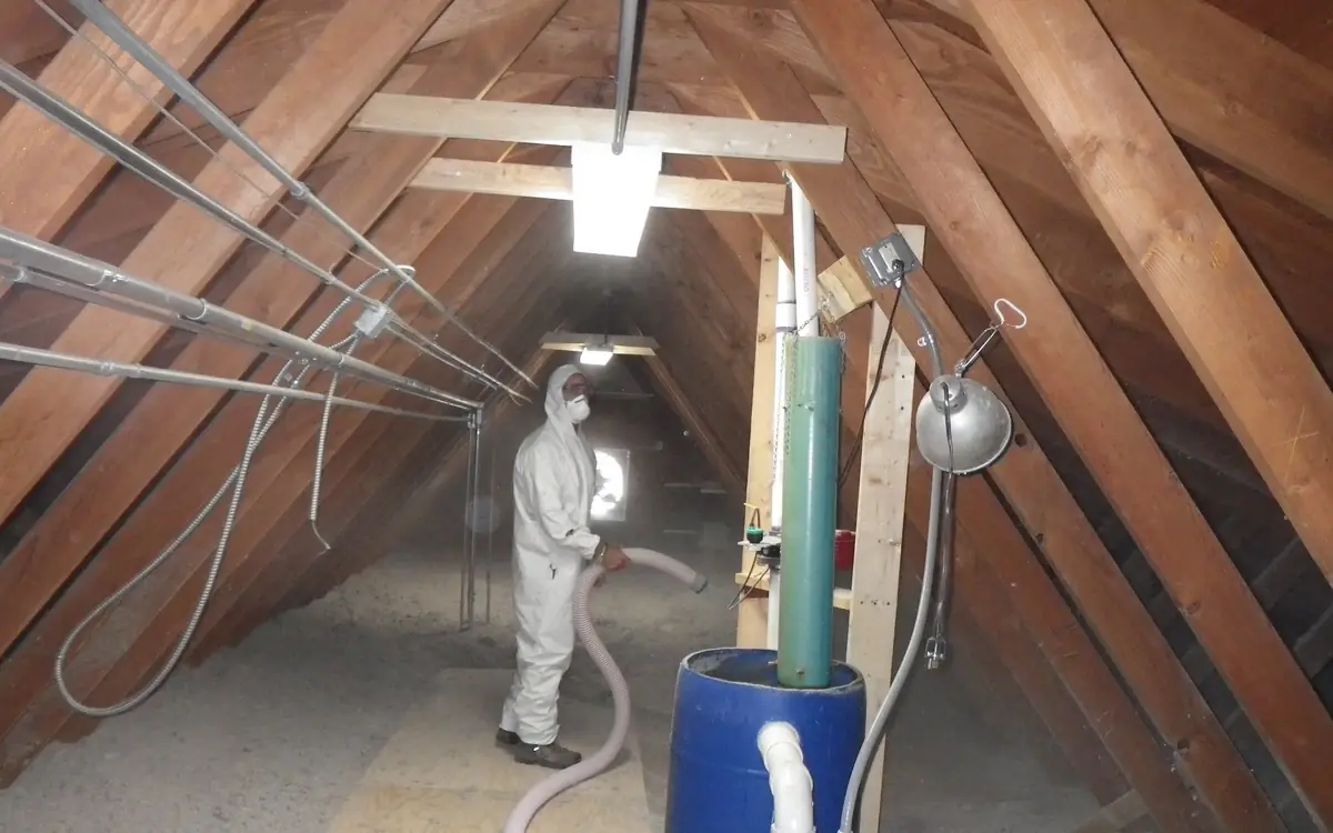
The thermostat is downstairs and it is telling the truth about downstairs
The call comes in the same shape every July. The hall thermostat holds its setpoint all afternoon, the equipment satisfies and shuts off exactly as it was asked to, and the back bedroom at the top of the stairs sits three or four degrees above that number at bedtime and stays there until well past midnight. Nothing is broken. A control installed on the floor that was comfortable is switching off a machine that has not finished with the floor that was not, and it will keep doing that faithfully for as long as it is left where it is.
Four unrelated mechanisms produce that gap, and each answers to a different piece of work. There is gain arriving downward from a roof that has been absorbing sun since mid-morning. There is buoyancy, which carries the warmest air in the house to its highest ceiling and parks it there. There is a distribution system whose trunk was sized around the ground floor and whose longest, most restricted branches happen to serve the rooms now complaining. And there is a latent load that makes an entirely honest reading feel oppressive. Buying capacity addresses one of the four, by force, at whatever the equipment costs plus whatever it draws for the next fifteen summers.
So the order below is diagnostic rather than alphabetical. What the ceiling is being asked to hold back comes first, because it is usually the largest term and the cheapest to shift. Then the route heat takes back out of the roof space. Then whether the room needs cooler air or merely moving air, which are different purchases at wildly different prices. Then what the moisture is doing to the perception of a number that already looks acceptable. Capacity comes last, and anyone who reaches it having done the rest arrives knowing what size is actually required instead of repeating whatever the previous installer guessed.
A week of logging beats an afternoon of standing in the room
A complaint is a feeling and a specification needs a trace, so the first purchase on this job is not a machine but two logging thermometers. Put one in the worst bedroom at pillow height, clear of the window and off the exterior wall, and clip the second beside the thermostat. Record at five or ten minute intervals across a run of hot days, note when the equipment runs, then overlay the two curves and look at the shape rather than the peak.
The shape names the mechanism. A bedroom that tracks the hall until mid-afternoon, diverges, and then holds its divergence for hours after sunset is being fed by heat stored in the structure above it, released long after the sun has stopped supplying it. A bedroom that only falls behind while the system is actually running has an air delivery problem, not a gain problem, because the divergence appears when the machine is trying and disappears when it stops. Two curves running parallel at an offset that never closes, in either state, describe a load that exceeds delivery around the clock. And a room within a degree of setpoint that still reads as unbearable is a moisture problem wearing a temperature complaint, at which point the whole conversation moves to the latent side.
- Site both loggers away from direct sun, supply grilles and lamps, and leave them undisturbed for the whole period.
- Log outdoor air as well if a third sensor is available, because the offset between attic and outdoor air is what sizes the roof argument.
- Note equipment run times, either from a controller log or from a clamp meter on the outdoor unit.
- Include at least one hot day with cloud and one clear one, since a stored-gain signature only separates from a straight load signature when the sun varies.
- Read the traces on a chart, not as a table of maximums, because every diagnosis above is a shape and none of them is a peak.
- Keep the file. It is the before condition that any later claim of improvement has to be measured against.
| Shape of the two curves | Most likely mechanism | What to change first |
|---|---|---|
| Diverges mid-afternoon, stays apart until the small hours | Stored gain through the roof and ceiling plane | Air sealing, then insulation depth, then a radiant barrier |
| Diverges only during equipment run time | Delivered airflow at the upstairs registers | Measure register flow and the closed-door return path |
| Parallel offset that never closes, running or off | Load genuinely above delivered capacity | Full room-by-room load calculation before any purchase |
| Temperature close to setpoint, room still reads oppressive | Latent load and short equipment run times | Run time and dehumidification, not a colder setpoint |
| Worst at the far end of the longest branch only | Duct sizing, leakage or an unbalanced damper | Flow measurement at each outlet, then balancing |
The ceiling is holding back a surface that has been in the sun since ten
A sunlit roof deck runs far above the outdoor air temperature by early afternoon, and it does not merely conduct that heat downward. It radiates it, across the open volume of the attic, onto the top surface of the insulation and onto everything else stranded up there, ductwork included. Insulation depth answers the conductive part of that exchange and answers it well. What it does not do is change the fact that the source temperature on the far side of it is nothing like the outdoor air the assembly was mentally sized against.
That distinction sets the order of the three attic measures, which is the single most common thing to get backwards on this job. Seal the ceiling plane first, because a reflective surface laid above an attic that is being fed conditioned air through unsealed top plates and light housings is a lid on an open pipe. Get depth to the level the adopted energy code requires next. Only then consider foil, and consider it as something that lowers the temperature the insulation is working against rather than as something that adds resistance of its own. An attic with thin or missing insulation is a poor candidate for a radiant barrier for exactly this reason: the cheaper measure has not been taken yet.
The property that makes the product work is emittance, published by the manufacturer against a named test method such as ASTM C1371, Standard Test Method for Determination of Emittance of Materials Near Room Temperature Using Portable Emissometers. The material class is covered by ASTM C1313/C1313M, Standard Specification for Sheet Radiant Barriers for Building Construction Applications, and in the United States what the packaging is permitted to claim is regulated by the R-value Rule at 16 CFR Part 460. A roll offering an adjective instead of a tested figure against a named method is offering nothing measurable.
Two site conditions destroy that tested figure and both are decided by where the foil is fixed. A low-emittance face in contact with another material conducts instead of reflecting, so the reflective side has to look into an air space and keep looking into one. And emittance lives in the top few microns of the surface, so dust ruins it. Those two facts favour stapling to the underside of the rafters, facing down into the attic, over draping the sheet across the top of existing insulation: the rafter position keeps its air gap on both faces and collects far less dust on the reflective side. The Oak Ridge National Laboratory and U.S. Department of Energy radiant barrier fact sheet is explicit about degradation of upward-facing installations over time. The horizontal position is quicker and cheaper on the day, and it is the position that quietly stops performing.
The horizontal position also raises a moisture question the rafter position does not. An unperforated sheet lying flat on top of insulation is a vapour retarder in a place nobody designed one, sitting where warm moist air from the house below arrives; perforated products exist precisely so that position stays permeable. Where a jurisdiction cares about vapour control in the attic assembly, that decision belongs to the adopted building code and the climate zone, not to whichever roll the merchant had in stock.
The quantity mistake worth catching before the order is geometric. Fixing to the rafter undersides means covering the sloping plane of the deck, which on any real pitch is meaningfully larger than the attic floor footprint people instinctively measure, and it is bought in fixed roll widths and lengths with an allowance for overlaps rather than in bare square metres.
Rolls come in fixed rectangles and the deck plane is larger than the floor below it, so put the measured sloping area in here — the overlap allowance is added for you, so do not add it twice — before the order goes out rather than after a bay is left short.
The underside roof deck area to be covered.
Radiant barrier rolls needed
4 rolls
- Area to cover (with overlap allowance)
- 1,771 sq ft
They open the calculator with your figures already in it
Attic Radiant Barrier Calculator: 4 rolls — shown in imperial, US market. The link sets both, so the result they see is the one on your screen.
Estimated cost — your price
This site holds no price list for this material — local prices vary too much to publish honestly. Enter your supplier's price and the result is costed with it.
What this calculation does not cover
- Roll size is fixed at 500 sq ft / 46 m² — a 4 ft / 1.2 m by 125 ft / 38 m roll — and there is no field to change it. Radiant barrier is also sold in wider and longer rolls, and in perforated, non-perforated, single-sided and double-sided grades that do not all carry the same coverage per roll. Take the area figure from the breakdown and divide it by the coverage printed on the roll you are actually buying.
- The area is used exactly as you type it. Nothing here derives the sloping rafter plane from a floor footprint and a roof pitch, so measuring the attic floor and entering that figure will under-order, and the shortfall grows as the pitch steepens. Gable ends, knee walls and dormer cheeks are not added either, so measure and add them yourself if you are lining them.
- The 10% allowance folded into the area is a flat figure that does not react to the shape of the roof or to how you cut the foil. Hips, valleys, dormers, chimneys, bracing and obstructed bays all generate more offcut than a simple gable, and cutting a 4 ft (1.2 m) roll into rafter-bay-width strips wastes more again. It also takes no account of the specific lap width a manufacturer's instructions call for at seams.
- This is a material count, not a performance calculation. It produces no emittance, R-value, temperature reduction, energy saving or payback figure, and it does not check the two site conditions that decide whether the foil does anything at all: the reflective face must look into an open air space, and it must stay clean, since dust on the surface raises emittance and kills the effect.
- Nothing about the assembly is checked. An unperforated sheet fixed in the roof plane acts as a vapour retarder where the design may not want one, eave baffles and the ventilation path must stay clear behind it, and clearances around recessed lighting, flues and chimneys are set by the manufacturer and the adopted code. Whether the installation is permissible in your climate zone is a code question this quantity does not answer.
Heat leaves the roof space by a path, or it does not leave
Whatever the deck radiates has to be carried away, and the carrying is done by outside air entering low at the eaves and leaving high at the ridge. The quantity that governs it is net free area, which is not the size of the hole: insect screen, louvre blades and baffles all obstruct, and the net figure is the one the vent manufacturer publishes for the specific product. Required area is expressed as a ratio of the attic floor area, halved where a vapour retarder is present and where intake and exhaust are properly split, and the ratio in force comes from the roof ventilation provisions of the International Residential Code as adopted and amended locally rather than from a figure carried in from another state.
Balance decides whether the path exists at all. A continuous ridge vent above soffits that have been packed solid with insulation is an exhaust with no intake, and it will find its makeup air by pulling it up through the ceiling from the bedrooms below. Gable vents left open alongside a new ridge vent are the mirror image of the same fault: the ridge takes the short, easy path from the gables and the roof plane above the soffit stops being scavenged at all. Fitting eave baffles and then confirming from inside that every bay is genuinely clear is the cheap half of this work, and it is the half most often skipped.
Powered attic ventilators deserve particular suspicion in exactly the situation this article describes. A fan pulling hard on an attic whose ceiling plane leaks will preferentially take the easiest air available, which is the conditioned air in the house, so the homeowner ends up paying a compressor to cool air that a second motor then exhausts through the roof. In a dwelling containing atmospheric combustion appliances that depressurisation stops being a billing question and becomes a safety one, which is why sealing precedes any powered solution rather than following it.
An unvented, conditioned attic is a legitimate alternative and a completely different design: insulation moved to the roof plane, the ducts brought inside the thermal boundary where they stop losing to a hot space, and vapour control determined by climate zone under the unvented attic provisions of the adopted code. What does not work is doing half of it. Blocking soffits and spraying some foam under the deck without meeting those provisions removes the drying path without replacing it, and the sheathing pays for that within a few seasons.
Net free area against attic floor area is the number that decides how many units to buy, and it belongs here because the figure it returns is a total to be shared: roughly half of it low at the eaves and half high at the ridge, rather than that whole area at either end.
The length of the attic floor, measured along the ridge; the page takes each eave and the ridge to be this long.
The width of the attic floor, wall plate to wall plate across the building.
The rule the vent area comes from: the IRC's ratio, Canada's, or the UK's and Australia's openings along the eaves and ridge.
The intake product, so the page can count it; the slot is a real product rated by its maker.
The exhaust product high on the roof: a ridge vent, or individual roof vents.
Net free vent area needed
6.5 sq ft (net free area)
R806.2 of the 2021 IRC: 1/150 of the attic floor. The code sets no split at this ratio; the page divides it evenly between intake low on the roof and exhaust high up, and keeps the intake at least equal to the exhaust bought, as GAF's balanced-ventilation guidance asks.
- Attic floor area
- 975 sq ft
- Net free area needed
- 936 in²
- Intake, low on the roof (eaves or soffit)
- 475 in²
- Exhaust, high on the roof (ridge or upper vents)
- 468 in²
- Intake as a continuous gap along both eaves
- 0.51 in
- Exhaust as a continuous gap along the ridge
- 1 in
- Intake vent to fit
- 6 vents (8 ft)
- Exhaust vent to fit
- 38 ft
- High-level share of the total
- 50 %
They open the calculator with your figures already in it
Attic and Loft Ventilation Calculator (Intake, Exhaust and Vent Count): 6.5 sq ft (net free area) — shown in imperial, US market. The link sets both, so the result they see is the one on your screen.
What this calculation does not cover
- Net free area is a rating, not a hole size. The counts divide by the rating printed on the product after its louvres, mesh and screens, and assume every vent is open: intake vents painted over, blocked by insulation slumped into the eaves with no baffle, or fitted over solid sheathing count for nothing.
- The shape is a simple gable roof with the ridge along the length. A hip roof has longer eaves and a shorter ridge, a roof with dormers, valleys or a firewall is several vented spaces, and each compartment is worked on its own; the fit checks along the eaves and ridge then need doing by hand.
- The US exception's vapor-retarder condition in climate zones 6, 7 and 8 is taken on trust: nothing here knows the climate zone or whether a Class I or II retarder is in place and continuous. Where either is missing, the 1/300 figure is not available and the 1/150 one applies.
- UK openings are BS 5250's for a cold roof with a high-resistance underlay, as makers restate them, taking the stricter maker at the 35° and 10 m (32.8 ft) boundaries; a breathable underlay, a warm roof, a lean-to or mono-pitch roof, and roofs of buildings other than dwellings each have their own provisions, and the underlay's certificate governs a breathable one.
- Australian openings are Table 10.8.3's, which applies in climate zones 6, 7 and 8 only, applied along both eaves of a dual-pitched roof. The roof space's 20 mm (0.8 in) minimum height, the cathedral ceiling's extra eaves opening, the unsarked tiled roof that needs no openings, and the exemptions for concrete roofs, structural insulated panels and BAL-FZ are the reader's to check against the clause itself.
- This restates a ratio or an opening size; it is not a code check, a moisture assessment or a performance calculation. Air leaking up from the house is usually the bigger moisture source, ember-resistant vents are required in some wildfire areas, and the authority having jurisdiction or building control decides what applies to a given roof.
Air across skin is a different purchase from air at a lower temperature
A ceiling fan does not cool a room. It adds a small amount of motor heat to it. What it changes is the rate at which a body loses heat to the air by convection and evaporation, and that is a large enough effect that ANSI/ASHRAE Standard 55, Thermal Environmental Conditions for Human Occupancy, allows elevated air speed to offset a higher operative temperature within the limits it tabulates. In a bedroom at night, that offset is frequently the entire complaint, which is why this section sits above the capacity section rather than below it.
The economics are worth stating plainly to whoever is paying, because they are not marginal. A fan draws a small fraction of what a compressor draws to achieve a comparable sensation for the person under it. The honest way to compare two fans is airflow in cubic feet per minute and efficiency in CFM per watt at each speed, both of which are published under the U.S. Department of Energy ceiling fan energy conservation standards and the ENERGY STAR Program Requirements for Ceiling Fans. Blade count, motor wattage on the box and pitch quoted without airflow are all marketing rather than performance.
Diameter comes off a room-area chart and mounting decides whether that diameter does anything. Blades want to sit in the occupied zone, which means a downrod on a high ceiling to bring them down to a working height, and a low-profile flush fixture where the ceiling is too low for one. A fan hugged tight to a sloped or vaulted ceiling stirs air well above the heads of everybody in the room and is a common reason an adequately sized fan disappoints. Minimum blade tip clearance to walls and minimum height above the floor come from the manufacturer's installation instructions, and electrically the outlet box has to be listed and marked for ceiling fan support under NFPA 70, National Electrical Code, Article 314 — a fan hung from an ordinary lighting box is not an upgrade, it is a fall waiting for a summer.
Two things need saying to the occupant, because they determine whether any of this survives the first week. A fan conditions people rather than rooms, so one left running in an empty bedroom is a small heater with a good story, and the switch belongs beside the door for that reason. And the reverse setting is a separate winter job at a low speed, destratifying a heated room, not a summer setting run backwards. Set against all that, the honest limit: elevated air speed raises the temperature at which a room is acceptable. It does not lower the temperature, and where the log shows a parallel offset that never closes it will not close it either.
Sizing starts with floor area and a published bracket, and it is worth running before the fixture is chosen — the bracket hands back a diameter and nothing else, so the mounting height that decides whether that diameter ever reaches the occupied zone is still yours to get right.
The floor area of the room where the fan will be installed.
Recommended fan diameter
44 in (44 in)
This is a general sizing chart — ceiling height, mounting type (standard, low-profile, or downrod), and room shape can shift the ideal size within the suggested range.
- Room area
- 220 sq ft
They open the calculator with your figures already in it
Ceiling Fan Size Calculator: 44 in (44 in) — shown in imperial, US market. The link sets both, so the result they see is the one on your screen.
Add the equipment this sizes
This result is a specification — 44 in (44 in) — not a quantity. Put the thing it sizes into your project: how many, what you call it, and your supplier’s price.
What this calculation does not cover
- Floor area is the only input. Ceiling height, room shape and where the fan hangs are not modelled, so a long or L-shaped room returns the same size as a square one of equal area — and a large or irregular space that would be better served by two smaller fans still gets a single recommendation.
- This is a comfort-airflow chart, not an electrical or structural check. It says nothing about the branch circuit, the switch or speed control, or whether the ceiling box the fan will hang from is rated to carry a fan's weight and movement — a standard lighting outlet box is not.
- The fan itself is not modelled. Blade pitch, blade count, motor type and rated airflow vary widely between fans of the same diameter, so two fans that both match this recommendation can move very different amounts of air.
- Blade-tip clearance is not checked. Because the answer comes from area alone, a narrow room can be handed a diameter that leaves less clearance to the walls than the fan's own instructions require — measure the shortest wall-to-wall dimension before ordering.
- Mounting height, downrod length and location rating are outside this calculation. A sloped ceiling, a low ceiling, or a damp or wet location such as a covered porch or bathroom each impose their own requirements on the fan you can install, whatever size the area suggests.
Why an honest reading still feels wrong
Cooling equipment removes water only while its coil is below the dew point of the air crossing it and while air is actually crossing it. Both conditions require run time. A unit comfortably larger than the load reaches setpoint quickly, shuts down, and then re-evaporates a good part of the condensate still sitting on the coil back into the house on the next start, which is the entire mechanism behind a house that is cold and clammy at the same time. Upstairs makes this worse rather than better, because the equipment satisfies a downstairs thermostat sooner than it would satisfy an upstairs one.
That is the specific failure oversizing produces, and it is why the sizing documents matter more here than any product choice. ANSI/ACCA Manual J, Residential Load Calculation, establishes the load room by room. ANSI/ACCA Manual S, Residential Equipment Selection, selects hardware against that load using the manufacturer's expanded performance data, which is where the sensible and latent split at the design condition actually lives; the nameplate total does not contain it. AHRI Standard 210/240, Performance Rating of Unitary Air-Conditioning and Air-Source Heat Pump Equipment, defines the conditions those published ratings were measured at, which is worth knowing before comparing two figures that were never measured the same way. A larger machine chosen to fix a hot bedroom routinely makes the humidity complaint worse while making the temperature complaint slightly better.
Upstairs also generates its own moisture, and the amounts are not trivial: bathrooms are usually on that floor, laundries sometimes are, and people sleep there for eight hours a night breathing and perspiring into a closed room. Local exhaust and whole-dwelling ventilation rates in residential work are set by ANSI/ASHRAE Standard 62.2, Ventilation and Acceptable Indoor Air Quality in Residential Buildings, and a bathroom fan that discharges into the attic instead of outside is a moisture source pretending to be a moisture control.
A portable dehumidifier is a reasonable answer for one floor, provided it is bought against the right number. The air in a bedroom holds far less water than people expect, so the initial pull-down from a humid reading to a comfortable one is quick and small. What actually sizes the machine is the continuous load: infiltration, occupants, adjoining wet rooms and moisture coming back out of soft furnishings. Ratings need care too, because the U.S. Department of Energy test procedure at 10 CFR Part 430 changed its test condition and roughly halved the printed capacity of identical hardware, while European ratings are usually quoted at a warmer and more humid condition still. Compare units only within a single standard, and take real extraction from the unit's own capacity table at the temperature and humidity of the room, because it falls as the room gets cooler and drier.
Two practical points close this out. Psychrometric relations behind all of the above are set out in the ASHRAE Handbook — Fundamentals, and CIBSE Guide A, Environmental Design, covers the equivalent ground for work in the United Kingdom. And the condensate has to go somewhere a person will not have to think about: a dehumidifier on a landing with a tank that needs emptying twice a day is a machine that gets switched off in week three, so plan a gravity drain or a small condensate pump at the same time as the unit.
Run this to see how little water the air itself is holding, because the small answer is the useful one: it proves the pull-down is the sprint and the continuous load is what the machine is really being bought for.
The floor area of the space being dried.
Average ceiling height — area × height is the air volume that holds the water.
Air temperature in the space. Warmer air holds more water at the same relative humidity.
What the hygrometer reads now, in %.
Where you want to hold the space — 50–55% is the usual comfort and mould-control band.
The litres-per-day figure on the unit's plate or box.
How much of the rated capacity your room's conditions actually deliver.
Water to remove from the air
0.0666 gal
This is the water in the AIR alone. Wet walls, wet contents and the continuous load from infiltration and occupants add far more over a day than the air itself holds — the pull-down being quick does not mean the job is small.
- Room air volume
- 127.41 yd³
- Water in the air now
- 0.31 gal
- Water in the air at the target
- 0.24 gal
- Pull-down time at derated capacity
- 0.43 hours
- Effective extraction rate
- 3.7 gal/day
They open the calculator with your figures already in it
Dehumidifier Water Removal Calculator: 0.0666 gal — shown in imperial, US market. The link sets both, so the result they see is the one on your screen.
Estimated cost — your price
This site holds no price list for this material — local prices vary too much to publish honestly. Enter your supplier's price and the result is costed with it.
What this calculation does not cover
- Only the water suspended in the air is counted. Moisture soaked into plaster, timber, screed, carpet and stored contents is excluded, and so is the continuous load — air leaking in from outside, ground moisture through a slab or crawlspace, showers, cooking and occupants. That continuous load, not the air's own water content, is what fills the tank day after day and what sizes the machine.
- This is not a drying-out calculation. Reaching the target room humidity does not mean a wet subfloor, wall cavity or plaster is dry; only a moisture meter in the material tells you that, and water still held in the fabric will push the room back up as soon as the unit stops.
- The pull-down time assumes a closed space with nothing adding moisture while the unit runs and a single extraction rate held constant throughout. It does not model infiltration during the run, doors opening, extraction falling as the room dries and cools, coil defrost cycles, or the unit's own humidistat cutting out short of the target.
- One temperature and one humidity are applied to the whole volume. Real spaces stratify — cold corners, outside walls, the space behind furniture and under a floor sit colder and wetter than the meter in the middle of the room, and reach the target long after it does.
- Not a condensation or mould-risk assessment. Mould grows at the surface humidity against a cold wall, window reveal or uninsulated slab, which can stay high while the room air sits comfortably at 55%. Judging that needs the surface temperature and a dew-point check, not a room average.
Air that never arrives, and air that cannot leave
If the log said the room only falls behind while the system runs, none of the previous sections is the fix. Start at the outlet and measure delivered flow at every upstairs register with a flow hood or capture bag rather than judging it by hand at the grille, which detects velocity and tells you almost nothing about volume. Compare what arrives against what the room was supposed to receive. Duct sizing for that comparison is governed by ANSI/ACCA Manual D, Residential Duct Systems, and outlet type, throw and placement by ACCA Manual T, Air Distribution Basics for Residential and Small Commercial Buildings — a technical manual rather than an ANSI standard, unlike the other three; a correctly sized branch feeding a badly chosen diffuser still dumps its air down the wall instead of across the room.
Then close the door, because that is how the room is actually occupied. A bedroom with a single supply and no return path pressurises as soon as the door shuts, the supply air leaves through whatever gaps it can find — very often into the attic — and an equal volume of makeup air arrives from somewhere equally unconditioned. A manometer reading across the closed door tells you in seconds whether it is happening. Undercuts, transfer grilles or jumper ducts solve it, and a jumper duct is the version that also keeps the noise down between rooms.
Finally, deal with the ducts themselves if they run through the space discussed three sections ago. Supply ductwork in a hot attic gives back cooling continuously through every unsealed joint and every thin patch of wrap, which is a straightforward way to lose a large share of what the equipment produces before it reaches the room that is complaining. Seal with mastic and reinforcing mesh rather than tape, insulate to the level the adopted energy code sets for ducts outside the thermal boundary, and where the roof geometry allows it bring the runs inside that boundary instead. Adding a motorised zone damper for the top floor is a legitimate move but not a free one: a system zoned without a workable strategy for the airflow the closed zone was carrying runs at higher static, gets noisy, and can drive the coil towards freezing.
When more capacity really is the answer
Some houses reach the end of that list and still need more cooling upstairs, and there is a recognisable signature for it: the two logged curves run parallel at an offset that never closes, measured flow at every register matches what the room was designed to get, the attic work has been done and verified, and the humidity has come under control without the temperature following it. That is a load exceeding delivery, and it is the one condition on this page that equipment genuinely fixes.
Even then, the fix is rarely a bigger central machine. A larger unit sized to satisfy the worst upstairs room will be badly oversized for the floor its thermostat lives on and will short-cycle its way straight back into the humidity problem the previous section described. Serving the top floor with dedicated equipment keeps the sizing honest for both floors, and the sizing still comes from a room-by-room Manual J for the rooms that unit will actually serve, followed by a Manual S selection against the manufacturer's performance data at the local design condition rather than at the rating condition.
Leave the evidence behind. The logger file from before the work, the register flow readings, the net free vent area and what was installed to reach it, the attic photographs taken before insulation buried anything, and the reason each measure was chosen or skipped. This is a complaint that gets re-diagnosed by someone else in a few years, and without that record the next person starts by quoting a bigger machine, which is where this one started.
Upstairs overheating take-off, in spending order
The list runs cheapest and most diagnostic first, and equipment last. Nothing below is priced here; local prices vary too much to publish honestly, so each line is the quantity you need before anyone can price it.
- Two logging thermometers and a week of hot weather — One at pillow height in the worst room, one at the thermostat, plus outdoor air if a third sensor is available. This is the before condition every later claim is measured against.
- Ceiling plane bypass schedule — Count and rough area of top plate joints, chases, light housings and the hatch. Sealing precedes both insulation depth and any reflective product, and it precedes any powered attic ventilator absolutely.
- Radiant barrier area on the deck plane, not the attic floor — The sloping rafter plane with an overlap allowance, converted to whole rolls. Confirm the product quotes emittance against a named test method before ordering.
- Net free vent area, split between intake and exhaust — Use the manufacturer's published net free area per unit, not the gross opening. Add one eave baffle per vented bay and verify from inside that the bays are actually clear.
- Fan diameter, mounting type and downrod length per room — Plus a fan-rated outlet box for each position. Record CFM and CFM per watt from the product literature so the fans can be compared on airflow rather than on motor size.
- Register flow readings and closed-door pressure readings — One per upstairs outlet and one per bedroom door. Drives the transfer grille or jumper duct count, and settles whether capacity is the problem at all.
Opens the calculators above on one screen with the dimensions from this article already filled in. Quantities only — this site publishes no price list, because local prices vary too much to publish honestly.