
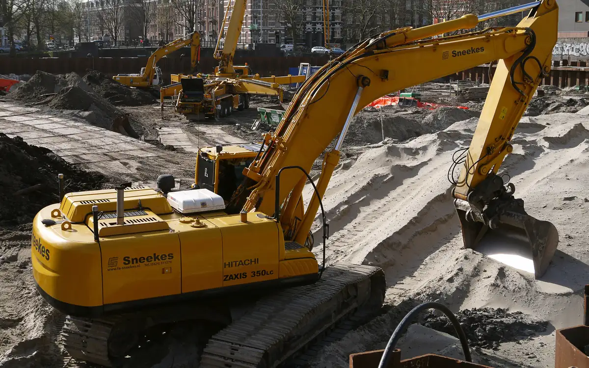
Four blows at three metres, and a shed to price
The report is forty pages and the part that matters is one column of a borehole log. Between about one metre and about seven, under a 6,000 m² distribution unit that has already been drawn, the standard penetration test is returning fours, fives and sixes. Below that it stiffens up properly. The architect has a ground-bearing slab on the drawings, the client has a date, and somebody has to say this week whether the foundation package is spread footings on treated ground or two hundred and forty piles with caps and ground beams under every line.
That is a different question from how a pile is designed, and it gets answered on different evidence. Pile design starts once the decision is made and works downward from a column load; this decision works outward from a soil profile and lands on a procurement route, a programme and a risk allocation. Get it wrong and the correction is not a revised calculation — it is a redesigned substructure, a different specialist contractor, and usually a claim. Get it right and nobody ever notices, which is why the reasoning behind it should be written down at the time rather than reconstructed later.
Three things move it, in this order. Whether the blow counts describe soil that is genuinely loose or merely shallow. Whether the soft layer can be persuaded to carry the building, which is a question about the soil's ability to hold something stiff in place rather than about the something. And, if it cannot, what a group of piles actually costs once you stop pricing them one at a time. Everything else on the decision sheet — programme, plant access, neighbours, contract form — modifies an answer those three produce.
A blow count measures the soil and the depth it was taken at
A raw N-value is not a soil property. It is the number of blows a 63.5 kg hammer falling 760 mm needed to drive a split-barrel sampler through 300 mm of ground, and that number responds to the confining pressure standing on the sample as much as it responds to how densely the grains are packed. The same sand, at the same relative density, returns a bigger number at eleven metres than at two. Reading a log without allowing for that is how a deep, genuinely loose sand gets waved through and a shallow, perfectly adequate one gets treated.
Two corrections sit between the field sheet and anything you can design with, and they are not interchangeable. The first is energy: the test is defined in ASTM D1586/D1586M, and the delivered energy varies with hammer type and operator, so field values are normalised to 60 per cent of theoretical free-fall energy to give N60. Automatic trip hammers commonly deliver well above 60 per cent and rope-and-cathead donut hammers well below, and a log that quotes N without saying which is a log with a question outstanding. Ask before correcting anything, because applying an overburden correction to a raw N that has not been energy-corrected produces a number with two errors in it and no way to separate them.
The second is overburden, which is what the calculator below does. It normalises N60 to a reference stress of one atmosphere using the correction factor from Liao and Whitman's 1986 paper on overburden correction factors for SPT in sand — the square root of atmospheric pressure over the effective vertical stress at the test depth — and caps that factor at 2.0 so a near-surface reading is not amplified into fiction. The cap binds whenever effective stress is below about 25 kPa, which on a typical profile means everything in roughly the top metre and a half comes out capped. Values from that zone are the least useful on the whole log and, awkwardly, they are usually the ones directly under a pad footing.
Take the running example. Field N60 of 5 at 2.5 m, in ground at 18 kN/m³ with the water table dipped at 1.5 m, gives an effective vertical stress near 35 kPa and a corrected N1,60 close to 8.4. The identical field value of 5, read at 11 m in the same profile, sits under about 105 kPa and corrects to roughly 4.9. One number on the sheet, two soils: the shallow one is mediocre, the deep one is loose enough to matter. Nothing about the fork is decidable until that separation has been made across the whole log.
Two limits on the result, and the calculator's own confidence note flags only the first of them. It applies the overburden step alone — rod length, borehole diameter and sampler-liner corrections are separate multipliers that a full interpretation needs, and the fines-content adjustment to an equivalent clean-sand value is a further step belonging to liquefaction work rather than to bearing capacity. And the whole apparatus is a granular-soil apparatus. Applying it to a blow count taken in soft clay is a category error dressed as arithmetic: N in a cohesive soil is a disturbed, rate-dependent index at best, and the strength you need there comes from a field vane to ASTM D2573/D2573M, an undrained triaxial, or a piezocone sounding to ASTM D5778. The most common way this page's decision goes wrong is a corrected N1,60 quoted with confidence for a layer of alluvial clay.
Enter an energy-corrected N60, not a raw field count, and take the effective stress at the test depth with buoyant unit weight below the water table. The stress field follows the metric/imperial switch, reading kPa or psf, so a report in either goes in as it stands; one given in tsf is multiplied by 2,000 first.
The energy-corrected field SPT blow count (already corrected to 60% hammer efficiency).
The effective vertical stress at the test depth.
Corrected N-value (N1,60)
21.2 (N1,60)
This applies overburden correction only — a complete SPT interpretation for liquefaction or bearing capacity analysis often needs additional corrections for borehole diameter, rod length, and sampler type, per the specific design method being used.
- Overburden correction factor (CN)
- 1.41
They open the calculator with your figures already in it
SPT N-Value Overburden Correction Calculator: 21.21 (N1,60) — shown in imperial, US market. The link sets both, so the result they see is the one on your screen.
What this calculation does not cover
- This applies the overburden correction and nothing else. It assumes the value you type is already energy-corrected to 60 per cent hammer efficiency, and it does not apply the rod length, borehole diameter or sampler liner corrections a full interpretation needs. A log that quotes N without saying which correction it already carries leaves that question open — settle it before entering the number, because correcting a raw field N here puts two errors in one figure with no way to separate them.
- The overburden correction and N1,60 are granular-soil tools. A blow count taken in soft clay, silt or organic ground and corrected this way is arithmetic with no soil property behind it — cohesive strength comes from a field vane, an undrained triaxial or a piezocone sounding, not from a corrected N.
- N1,60 is an input to liquefaction and settlement procedures, not the assessment itself. It does not apply the fines-content adjustment to an equivalent clean-sand value, and it says nothing about cyclic stress ratio, earthquake magnitude, or the seismic demand at your site.
- The 2.0 ceiling on CN binds at any effective stress below 25 kPa, so every reading from the shallowest part of the log comes back as exactly twice the entered N60 and stops responding to depth at all. That ceiling is a practice convention rather than part of the original correction relation, and some procedures cap it lower — a shallow result here can sit above what those methods would allow.
- It takes the effective vertical stress as given. It does not derive it from depth, unit weights and the water table, and it does not check that you used buoyant unit weight below the water table — entering total stress instead of effective overstates the stress and understates the corrected N-value. The field is in kPa and does not follow the site's metric/imperial switch, so convert a stress quoted in psf or tsf before it goes in.
Six ways out, and what each one needs to be true
With a corrected profile in front of you the options stop being a list and start being a filter. Each one depends on a condition that is either satisfied by this site or is not, and the fastest way through the decision is to knock out the ones whose condition fails rather than to price all six. The table below is that filter. It is deliberately silent on cost, because unit rates for ground treatment and piling move with region, rig availability and access more than they move with soil type, and a published rate would be wrong somewhere within a week.
One entry deserves a note before you read it. Doing nothing is a real option and it is under-considered, because the settlement a warehouse floor can tolerate is often larger than the settlement a designer instinctively allows. A single-storey portal frame on pad footings, with movement joints in the slab and flexible service entries, will accept differential movement that would crack a rendered residential elevation. The serviceability criterion belongs to the structure, not to the ground, and it should be established before the ground is condemned.
| Route | Only works if | Proved by |
|---|---|---|
| Leave it and spread the load | Bearing pressure at footing level satisfies the bearing check, and the structure tolerates the resulting settlement | A bearing capacity analysis against measured strength, with the presumptive values in IBC Table 1806.2 used only as a first screen |
| Dig it out and replace it | The soft layer is shallow, the excavation stands or can be battered, and groundwater is controllable | Compaction testing on every lift of the replacement fill, against a Proctor maximum from the same material |
| Preload, with vertical drains if needed | The layer is compressible rather than weak, and the programme has months rather than weeks in it | Settlement plates and piezometers read against the prediction; drain installation to BS EN 15237 |
| Vibro stone columns | The surrounding soil can confine a column of stone — so not in very soft cohesive soil, and not through significant peat or organics | Zone load tests and post-treatment cone soundings between column positions, per BRE BR 391 and the project specification |
| Rigid inclusions or deep soil mixing | The soft soil cannot confine stone, but a load transfer platform can spread the structure's load onto stiff elements | Element integrity and strength testing appropriate to the technique; deep mixing executed to BS EN 14679 |
| Pile through to a competent stratum | There is a competent stratum within reach, and the structure can accept caps, ground beams and a suspended slab | Static or high-strain dynamic load testing on a proportion of the works piles, to the frequency the specification sets |
A stone column is only as stiff as the ground squeezing it
Vibro replacement is the option most often misunderstood by people pricing it, because the mental model is wrong. A stone column is not a small pile. It is a column of compacted crushed rock with no binder and no tensile capacity, and when load comes onto it, it does not punch downward — it bulges outward in the upper couple of diameters, and it stops bulging only when the soil around it pushes back hard enough. The capacity of the column is therefore set by the lateral resistance of the soft soil it was installed to avoid relying on. That circularity is the whole design problem, and it explains the technique's one hard limit: below some undrained shear strength, the surrounding soil cannot confine the stone at all, and the column simply spreads into the ground under load. The figure commonly quoted as a lower bound for unencased columns is around 15 kPa, and organic layers of any real thickness are a separate exclusion regardless of measured strength. Take the actual limit from the specialist's design and the execution standard, BS EN 14731, rather than from a rule of thumb — but knowing that the limit exists is what stops a scheme being priced on ground that will never accept it.
What the columns buy, where they work, is mostly settlement reduction rather than bearing capacity. A treated block behaves as a composite: the stiff columns attract a disproportionate share of the applied stress, the soft soil between them carries the rest at a reduced level, and the composite settles less than the untreated soil would. The proportioning is governed by the area replacement ratio — the column cross-section divided by the ground area each column serves — together with the stiffness ratio between stone and soil. Priebe's 1995 method in Ground Engineering is the design route most often used for that step, and the FHWA Ground Modification Methods Reference Manual (Geotechnical Engineering Circular No. 13) sets out the alternatives. The columns also work as vertical drains, which shortens the drainage path in a consolidating layer and is a genuine second benefit rather than a sales point.
The replacement ratio is where the estimate lives, because it is the only variable in the whole scheme that the client is actually buying. On a triangular grid each column serves an area of the square of the spacing times root three over two, and the ratio falls off with the square of spacing — which means the relationship between improvement and money is steep in a direction that surprises people. Eight-hundred-millimetre columns at two-metre centres give a ratio of about 0.145, which is roughly 29 columns per hundred square metres. Tightening the same columns to reach 0.25 puts them at about 1.52 m centres and about 50 columns per hundred square metres. The stone quantity goes up by the same proportion, and so does the rig time, and the treated depth multiplies all of it.
Two cautions on reading the number the calculator returns. It is a geometric ratio and nothing more: it is an input to a settlement method, not a settlement, and no value of it certifies anything on its own. And the composite behaviour it feeds assumes a unit cell — one column surrounded by identical columns in every direction, sharing load with an infinite grid. Under a strip or pad footing carrying three or four columns, the outer ones have soft ground on one side instead of a neighbour, they are less confined and less stiff, and the unit cell overstates what they deliver. Small groups under isolated footings are designed differently from a raft-wide treatment, and a ratio carried across from one to the other is optimistic in the direction that shows up as differential settlement.
The last thing to fix before this option is priced is the working platform. The rig is heavy, it works from the surface, and on the ground being treated it needs a granular platform designed for it — which is a separate quantity, a separate specification, and on a wet site a separate argument about who pays for it. That platform usually stays and becomes the load transfer blanket between the column heads and the slab, so it appears twice in the logic and should appear once in the bill.
Treated ground under a pad, cut from the slab to the toes
- Slab and pad footing — the structure's contact with the treated block, and the level at which bearing pressure is checked before any of the treatment below is specified Footing Soil Bearing Pressure Checker
- Granular load transfer blanket — spreads footing load between column heads and doubles as the working platform the vibro rig stands on, so it is bought once and used twice Gravel Base Layer Tonnage Calculator
- Compacted stone columns — carry a disproportionate share of the stress and hold it only while the surrounding soil confines them against bulging near the top Vibro Stone Column Area Replacement Ratio Calculator
- Soft soil between the columns — left in place and still carrying load at a reduced stress, which is why the composite settles rather than stopping dead Primary Consolidation Settlement Calculator
- Competent stratum at the toes — the layer the columns are taken into, described by blow counts that mean nothing until they are normalised for the overburden above them SPT N-Value Overburden Correction Calculator
Both inputs are lengths and follow the measurement system, and the answer is dimensionless, so a grid entered in feet returns the same ratio as the same grid in metres. It assumes a triangular grid — a square grid at the same spacing serves a larger tributary area and gives a lower ratio, so do not read this against a square layout.
The installed diameter of each stone column.
The center-to-center spacing between columns on a triangular grid.
Area replacement ratio
0.1342 (as)
- Column cross-sectional area
- 4.91 ft²
- Tributary area per column
- 36.59 ft²
They open the calculator with your figures already in it
Vibro Stone Column Area Replacement Ratio Calculator: 0.1342 (as) — shown in imperial, US market. The link sets both, so the result they see is the one on your screen.
What this calculation does not cover
- The diameter entered is the nominal design diameter, not the column that gets built. Vibro columns bulge in soft layers and neck in stiff ones, and the achieved diameter is normally back-calculated from the stone consumption recorded for each column. Because area goes with the square of the diameter, a 0.8 m column that finishes at 0.9 m raises the ratio from 0.145 to 0.184 at 2.0 m centres.
- The tributary area is hard-coded as (√3/2) x spacing², which is the equilateral triangular grid and nothing else. Feeding a square-grid spacing into this page returns a ratio about 15% higher than the correct figure, because a square grid's tributary area is spacing² — 0.8 m (2.6 ft) columns at 2.0 m (6.5 ft) centres give 0.145 on a triangular grid but 0.126 on a square one.
- The area replacement ratio is a plan geometry fraction, not a settlement or bearing capacity result. Settlement improvement methods such as Priebe's also need the friction angle of the stone, the stiffness or undrained shear strength of the soil and the stress concentration that develops between column and soil, and this page takes no soil parameter at all — it returns the same ratio for a dense sand and for a clay too soft to confine a column. Two sites with an identical ratio can settle by very different amounts.
- The tributary area assumes a large regular grid in which every column is ringed by neighbours. Columns at the perimeter of a small group get less lateral confinement, which is why an extra row of columns beyond the loaded footprint is commonly specified, so for a pad footing carrying only a handful of columns this ratio overstates the improvement actually acting at the edge.
- This is a plan-area quantity that carries no information about depth. It does not distinguish columns founded on a competent stratum from floating columns, and it says nothing about compression of the untreated soil below the column toes, which frequently governs total settlement. It also takes no account of the stone's drainage function in accelerating consolidation, or of the densification of surrounding granular soil that governs liquefaction mitigation designs.
Piling prices by the group, never by the pile
If the soft layer is too weak or too organic to confine stone, and there is no programme for a preload, the load goes past the problem instead of through it. The instinct at that point is to take a single-pile working capacity, divide the column load by it, round up, and multiply by a rate. That estimate is wrong in a specific and expensive direction, because piles close enough together to share a cap are also close enough together to share soil, and the sum of what they can each do alone is more than what they can do together.
The Converse-Labarre expression is the usual first pass at how much is lost. It reduces the sum of individual capacities by a factor derived from the angle whose tangent is the pile diameter over the centre spacing, scaled by the number of interior contacts in the grid. Its behaviour is worth knowing before you use it: it depends only on that ratio and the grid counts, and knows nothing about soil type or installation method. That is a real limitation. Driving a displacement pile into loose granular soil densifies the ground between piles, and a driven group in sand can genuinely exceed the sum of its parts — an efficiency above one — which this formula cannot produce. Bored piles in the same ground relax it, and the formula is not calibrated for that either. It is a screening tool from the foundation engineering literature, set out among other places in Bowles's Foundation Analysis and Design, and it should be labelled as one on the calculation sheet.
For friction piles in a cohesive soil, the check that usually governs is not this one at all. It is block failure: the group, its cap and the soil enclosed between the piles treated as a single large pier, with shear resistance around the block perimeter and end bearing across its base. Where the piles are close and the group is large, that block capacity falls below the reduced sum of the individual piles, and the block is what you design to. Run both and take the lower — which is where the calculator's own confidence note points and what the notes under it say outright, and they say it because the arithmetic the calculator does is the one more likely to be quoted in isolation.
Now the part that actually moves an estimate. Take 400 mm piles on the conventional three-diameter minimum spacing, 1.2 m centres, in a three-by-three group: the efficiency comes out near 0.73, so more than a quarter of the paid-for capacity has gone before anything is built. Recovering it by widening to four diameters lifts efficiency to about 0.79, but the pile centres now span 3.2 m instead of 2.4 m, and on the geometry alone the cap grows from roughly 3.4 m square to roughly 4.2 m square — about half as much concrete, reinforcement, excavation and blinding again, per cap, across every column position on the grid. That trade is the substance of the piling option, and it is invisible if the estimate stops at a rate per metre.
Two more consequences follow from the same formula and both point the same way. It penalises large groups hardest — a five-by-five at the same spacing drops to about 0.67, while a two-by-two holds near 0.80 — and large groups are also where block failure is most likely to govern, so for once the screening check and the governing check agree about which direction the risk lies in. And a cap sitting on soft ground is itself a structure that has to be detailed for the ground settling away beneath it, with a void former where that movement is real. Where the soft layer is also still consolidating under placed fill, the drag it hangs on every shaft is a further load rather than a further capacity, and it is worked through in the guide on sizing driven piles in soft clay rather than repeated here.
Diameter and spacing are lengths and convert with the measurement system; the row and column counts are plain integers. Use the result as a screen, then check block failure separately for a friction group in clay and design to whichever is lower.
The diameter of each pile in the group.
The center-to-center spacing between adjacent piles.
The number of pile rows in the group.
The number of pile columns in the group.
Group efficiency factor
0.727 (Eg)
The Converse-Labarre formula is a widely-used but empirical approximation — some geotechnical engineers consider group efficiency for friction piles in clay more reliably assessed with a block failure check instead, especially for closely-spaced groups.
- θ = arctan(d/s)
- 18.43 °
They open the calculator with your figures already in it
Pile Group Efficiency Calculator (Converse-Labarre): 0.7269 (Eg) — shown in imperial, US market. The link sets both, so the result they see is the one on your screen.
What this calculation does not cover
- The result is the Converse-Labarre per-pile efficiency and nothing else. It does not check block failure, where the piles and the soil between them fail as one mass — for friction piles in clay at close spacing that check often governs and gives the lower capacity, so it has to be run separately and the lower of the two used.
- The formula reads only diameter, spacing and grid size. It knows nothing about soil type, pile length or installation method, so it returns the same reduction for a driven pile in dense sand as for a bored pile in soft clay. Driven piles in loose to medium sand can reach an efficiency of 1.0 or higher because driving densifies the ground between them, and piles end-bearing on rock see essentially no group reduction — this calculator never returns either.
- This is a capacity reduction factor, not a foundation design. It applies no factor of safety or resistance factor, and it covers no settlement check — a pile group settles more than a single pile carrying the same load per pile, and settlement rather than capacity often governs the design.
- It assumes one rectangular grid of identical vertical piles at a single uniform spacing in both directions. Staggered or triangular layouts, raked piles, mixed pile diameters within the group, irregular group outlines and different row and column spacings are all outside the model.
- It applies no minimum spacing check. Buildable centre-to-centre spacing is set by the governing code and by piling rig tolerance, and this calculator will return a number for spacings closer than those permit — including spacings below one pile diameter, which is not a pile group at all.
The comparison is not made in the geotechnical package
The two options do not compete on the line where people compare them. Ground improvement is priced per square metre of treated area; piling is priced per metre of pile. Setting those two rates side by side answers nothing, because the choice between them changes the superstructure. Improved ground usually keeps pad footings and a ground-bearing slab. Piles usually bring pile caps, ground beams spanning between them, a suspended or void-formed slab, deeper excavation, more reinforcement and a longer trade sequence before the frame can start. That difference frequently exceeds the difference between the two specialist quotations, and it lives in the structural and groundworks packages where nobody looking at a geotechnical comparison is reading.
Programme is the second axis and it is not symmetrical. Preloading is the cheapest technique on this page in materials and the most expensive in time, and it is only available if the decision is made early enough for months of surcharge to sit inside the programme. Vibro treatment is fast once mobilised and covers large areas quickly, which suits a big footprint. Piling is fast per pile and heavy on mobilisation, set-up and testing time, which suits a small footprint with high loads. A decision taken late has already eliminated one of the three regardless of what the ground says.
Third is who carries the risk, and this is the part that should be settled before a tender goes out rather than argued after one comes back. Ground treatment is very often let as a performance specification: the specialist designs the grid against a stated settlement criterion and warrants the result. That only works if the criterion is written properly — total and differential settlement, over a defined structure and period, measured by a defined method — and if the ground investigation the specialist is designing from is adequate for the area being warranted. A performance specification issued with three boreholes across six thousand square metres transfers a risk the specialist will either price heavily or decline, and the pricing of unknown ground is almost always more expensive than the site investigation that would have removed it.
- Establish the structure's settlement tolerance first, from the frame and the finishes, before deciding whether the ground is a problem at all.
- Separate energy correction from overburden correction on every SPT value, and stop applying either to blow counts taken in cohesive layers.
- Correct the granular blow counts to N1,60 across the full log depth, so that the loose layers and the merely shallow ones are told apart.
- Get strength for the cohesive layers from vane, triaxial or piezocone data, and confirm whether any organic or peat horizon exists at any thickness.
- Screen out the routes whose governing condition this site fails, and price only the ones that survive.
- For a stone column scheme, set the replacement ratio from the settlement method, then convert it into a column count, a stone quantity and a treated depth before any rate is applied.
- For a piling scheme, apply group efficiency and a block check to get pile numbers, then size the caps and ground beams and carry those quantities into the comparison.
- Compare the two on total substructure cost, programme and residual risk — never on the specialist rates alone.
- Write the settlement acceptance criterion and the verification regime into the tender documents before either option goes out to price.
What overturns the decision after it has been priced
Obstructions are first, and they are almost always in made ground. A brownfield platform with old foundations, slabs, culverts or a demolition arisings layer will stop a vibro poker and deflect a driven pile, and neither problem appears on a borehole log that happened to miss them. Trial pits are cheap and answer this directly; a rotary probe grid across the footprint answers it better. Where the obstruction layer is known and shallow, pre-boring or pre-excavation becomes a line in the specification rather than a variation halfway through the works.
Contamination and ground gas can rule out an option outright rather than making it dearer. A column of open-graded stone driven through a low-permeability horizon is a vertical pathway, and where that horizon is separating contaminated soil or perched leachate from an aquifer beneath, the regulator's position on creating that pathway is the constraint — not the geotechnics. The same geometry is sometimes exactly what is wanted on a gassing site, since the columns vent, but that is a decision for the gas protection strategy and the environmental permit rather than an incidental benefit to be assumed.
Vibration and the neighbours decide more of these than engineers expect. Depth vibrators and piling hammers both put energy into the ground; where the site adjoins housing, a listed structure or vibration-sensitive equipment, the assessment and monitoring obligations under BS 5228-2 can push a scheme toward a bored or augered technique that would otherwise be the wrong answer on price. Establishing what is next door, and what it is sensitive to, belongs at the same stage as reading the log.
Finally, and most often, what overturns the decision is more information. Where a loose saturated sand sits below the water table in a seismic region, the corrected blow counts are the entry point to a liquefaction assessment rather than a bearing calculation, and the fork changes shape entirely — densification becomes a mitigation measure in its own right, and end-bearing piles founded below the liquefiable layer still have to be checked for the loss of lateral support if it liquefies. Where the log has too few holes to characterise a large footprint, the correct next step is neither of the two options on this page: it is a second phase of investigation, priced against the cost of the contingency both specialists would otherwise carry. That is rarely the popular recommendation in the week the foundation package is due, and it is frequently the cheapest thing on the table.
What the fork needs on the desk before it can be called
Six things, each of which changes which option survives rather than refining one that already has. Assemble them before any rate is asked for, because a specialist asked to quote without them prices the uncertainty instead.
- The SPT log with the hammer type stated — Energy correction to N60 comes before overburden correction and cannot be reconstructed afterwards. If the log does not name the hammer, that is one email, not an assumption.
- Strength data for every cohesive layer — Vane, triaxial or piezocone. Blow counts do not describe a clay, and the stone column route stands or falls on the undrained strength of the layer being treated.
- A stated presence or absence of organics — Peat and organic horizons exclude unencased stone columns independently of measured strength, so the log has to say so rather than be silent about it.
- The structure's settlement tolerance, from the frame designer — Total and differential, with the period and the measurement method. This is the acceptance criterion a performance specification is warranted against, and it belongs in writing before tender.
- Water table depth with the date it was dipped — It sets the effective stress every corrected blow count depends on, and it governs whether an excavate-and-replace option is buildable at all.
- Obstruction and made-ground information from trial pits — Neither a poker nor a hammer negotiates a buried slab. Found before tender it is a specification clause; found afterwards it is a variation and a delay.
Opens the calculators above on one screen with the dimensions from this article already filled in. Quantities only — this site publishes no price list, because local prices vary too much to publish honestly.