
The job
Modelled, not recorded. Every figure on this page is re-run through the calculator it names whenever the site is built; the estimate is worked, but no job was carried out, so the last section gives the mechanism of each likely error rather than a measured overrun.
A quote for topping up a loft often runs to one line, so many rolls of mineral wool, and in this loft the rolls are the sixth of seven steps. Four of the steps before them deal with things the 170 mm (6.7 in) cross layer is about to cover: the open joints at the partition heads and around the soil-stack boxing, the eaves bays, the pipework round the cistern, and the chord tops the storage deck has to stand on. Once that layer is down across the chords, reaching any of them means rolling it back and relaying it. The page follows that sequence, which runs the opposite way to a shopping list.
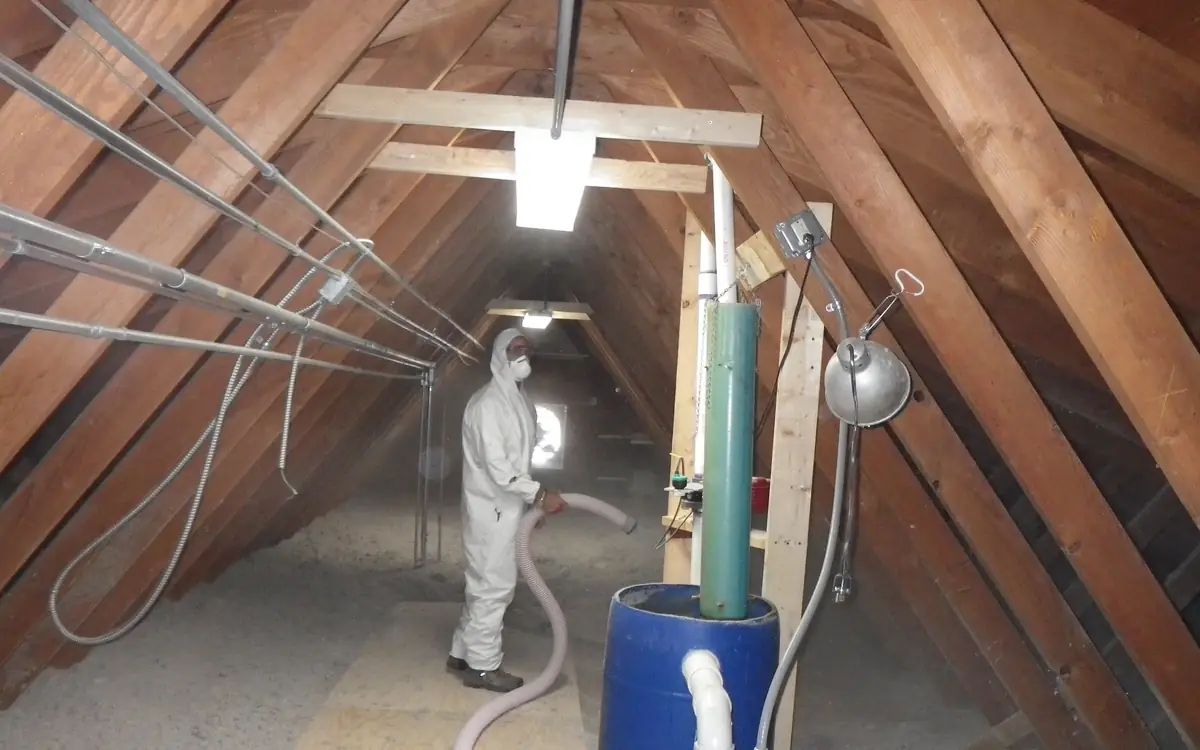
The job: a two-storey house with wet-plastered masonry cavity walls and a 7 × 9 m (23 × 29.5 ft) loft under a duo-pitch trussed-rafter roof, gables at the short ends and eaves along both long sides. The trusses stand at 600 mm (23.6 in) centres over a plasterboard ceiling, with 100 mm (3.9 in) of old mineral wool quilt between bottom chords 97 mm (3.8 in) deep. The cold-water storage cistern and its pipework are up there, and a boarded storage area is wanted near the hatch.
270 MM IS AN ANSWER, NOT A STARTING POINT. It is the figure usually quoted for a mineral wool loft, but the figure that counts is the depth the U-value sum asks for, less what is already there. At a conductivity of 0.044 W/m·K (0.31 BTU·in/hr·ft²·°F) the thickness calculator puts the whole layer at 264 mm (10.4 in) for a target of 0.16 W/m²K (0.028 BTU/hr·ft²·°F), so the stock depth above it is 270 mm: the 100 mm between the chords plus a 170 mm (6.7 in) roll laid across them. The same sum gives the existing 100 mm about 0.39 W/m²K (0.070 BTU/hr·ft²·°F), which is the size of the improvement being bought.
THE SECOND IS WHAT THE EXTRA 170 MM DOES TO THE ROOF SPACE ABOVE IT. With less heat crossing the ceiling, the air round the cistern, the felt and the rising main follows the weather outside far more closely than it did over 100 mm of quilt. Warm, damp air rising through an unsealed partition head then meets a colder underlay, and a pipe that used to lie in the lukewarm air just over the old quilt is left out in the open void. Both are reasons the sealing, the eaves trays and the lagging are ordered ahead of the rolls here.
WHAT THIS PAGE IS, AND WHERE THE SITE RUNS OUT. No loft was insulated to write it: the house is a model, and each figure on it was produced by the calculator named at its step. Three gaps are named rather than filled. The attic insulation upgrade calculator works in US R-per-inch for blown fill, so the depth comes from the U-value page instead. The attic ventilation calculator applies the US 1:150 rule rather than BS 5250, so eaves ventilation is described without a figure. And the attic insulation takeoff linked here works in US R-values, with blown fill as its main row and batts as the alternative; it has no U-value step, no lagging and no storage deck.
What was measured, and how
Loft floor plan, taken at ceiling level
9.0 m along the ridge × 7.0 m across the span (29.5 × 23 ft): 63 m² (678 sq ft) of ceiling
Measured wall plate to wall plate across the span and gable to gable along the ridge, on the chord tops rather than from outside the house. An external measurement adds the wall thickness twice and overstates the ceiling; one taken along the roof slope overstates it further.
Depth of the insulation already there
100 mm (3.9 in) of mineral wool quilt, just proud of the chord tops
Read with a rule pushed down to the plasterboard at several points spread across the loft, none of them near the hatch. Quilt beside the hatch has been knelt on for years and reads thin; a reading off the lofted top of one roll reads thick. The settled figure is the one the sum uses.
Truss centres and bottom chord size
Trussed rafters at 600 mm (23.6 in) centres, bottom chords 35 × 97 mm (1.4 × 3.8 in)
Centres measured over five bays and divided, never read from one gap, since the spacing wanders by a few millimetres from one frame to the next; chord size taken at two or three trusses. The spacing sets the eaves tray count and the leg positions, and the chord depth sets how high the deck must sit.
Target U-value and the roll's conductivity
0.16 W/m²K (0.028 BTU/hr·ft²·°F) taken as the target for this example; λ 0.044 W/m·K (0.31 BTU·in/hr·ft²·°F) for the roll
The target is whatever the specification for the work sets; where the job is regulated, that is the edition of Approved Document L in force for the address. The conductivity comes from the roll's own declaration. A target lifted from an article, or the conductivity of a different product, changes the depth the sum returns.
Roll cover, read from the label
6.0 m² (65 sq ft) per 170 mm (6.7 in) roll, assumed for this example
Taken from the pack for the exact thickness and conductivity being bought. The usual mistake is using the cover printed for a different depth, since two thicknesses of the same maker's roll cover quite different areas per roll.
Everything that passes through the ceiling
One boxed soil stack of 0.09 m² (1 sq ft); 12 m (39 ft) of stud partition, its head joint open to the loft on both faces; four bathroom downlights 100 mm (3.9 in) across, all marked for insulation contact; eight cable and pipe holes; no flue
Walked with a torch before anything is disturbed, counting a bored hole once however many cables share it, and measuring the soil-stack boxing and the partition heads. Missing the small holes is the common error: nothing on the ceiling below shows where they are, and the first roll hides them.
Pipe runs in the loft, measured along the pipe
12 m (39 ft) of 15 and 22 mm copper: the rising main, the cistern's cold feeds and the open vent from the cylinder
Taken along each pipe from where it rises through the ceiling to the cistern and back down, including the drops and the vent over the cistern. A straight line from hatch to cistern misses the vertical runs and the bends, which are where lagging is hardest to fit.
The storage island, set out to the chords
3.6 m along the ridge × 1.8 m across (11.8 × 5.9 ft); deck underside 173 mm (6.8 in) above the chord tops to clear the 270 mm (10.6 in) finished depth, plus a working clearance
Placed under the ridge between the truss web feet, where there is headroom, with its length a whole number of 600 mm bays so both ends land on a chord. The working height is what remains between the finished boards and the nearest web crossing above them, so it is checked after the deck height is added; the ridge height tells nothing.
The takeoff, in order
Each step needs something from the one before it, which is why the order is part of the answer.
Set the finished depth from the U-value target
- Needs
- The target U-value and the roll's declared conductivity from the measurements, with the plasterboard ceiling entered as the only other layer: 12.5 mm (1/2 in) of board, about 0.06 m²K/W (R-0.34). Nothing is ordered before this, because the top-up thickness is this answer less the 100 mm already between the chords.
- Produces
- 264 mm (10.4 in) of mineral wool in all to reach 0.16 W/m²K (0.028 BTU/hr·ft²·°F), with the loft treated as a well-ventilated void so nothing above the insulation counts. The stock depth above it is 270 mm — 100 mm existing plus a 170 mm roll across the chords — and the board box shows 270 mm reaching 0.156 W/m²K (0.0275 BTU/hr·ft²·°F) before the chords' bridging is counted. That margin of 0.004 W/m²K (0.0007 BTU/hr·ft²·°F) is thin enough for the bridging to use up; the next stock size, a 200 mm (7.9 in) roll making 300 mm (11.8 in) in all, returns 0.141 W/m²K (0.025 BTU/hr·ft²·°F).
Result264 mm (10.4 in) of mineral wool in all, so 270 mm (10.6 in) is the stock depth above it
Insulation Thickness for a Target U-Value Calculator (BS EN ISO 6946)Seal the ceiling before the new layer buries it
- Needs
- The ceiling survey, and the depth from step one: at 270 mm (10.6 in) every penetration is buried for good, and the colder void the top-up creates turns air leaking through them into a condensation risk as well as a heat loss.
- Produces
- 4 tubes of sealant for a 29.1 m (95 ft) bead round the partition heads, the soil-stack boxing and the downlight rims, one can of foam for the eight small holes, and 0.1 m² (1.1 sq ft) of rigid board to close the boxing. The partition joint is entered as 24 m (79 ft), both faces of the 12 m of stud wall, and makes up most of the bead. The downlights are in the bead only because all four are marked for insulation contact; an unmarked fitting would leave it and need a cover of its own. The external walls are left out: on wet-plastered masonry the plaster closes the ceiling edge, there is no timber head plate to bead, and along each eave that edge sits at the foot of the slope beside the wall plate, out of reach.
Result4 tubes of sealant for 29.1 m (95 ft) of bead, plus one can of foam
Attic Bypass Sealing Material CalculatorFit an eaves tray in every bay ahead of the cross layer
- Needs
- The 270 mm (10.6 in) depth from step one, which will reach the underside of the roof at the eaves unless something holds it back, and the 600 mm truss centres and 9 m eaves from the measurements.
- Produces
- 15 trays per 9 m (29.5 ft) eave, 30 for the two long sides, each holding a clear path from the eaves over the insulation. How much ventilation the roof needs is set by BS 5250 and by Approved Document C's provisions for roofs, which no calculator on the site works; the trays only keep the path open.
Result15 eaves trays per 9 m (29.5 ft) eave, 30 for the two eaves
Attic Rafter Baffle/Chute Count CalculatorLag the cistern pipework that will sit above the new layer
- Needs
- The pipe runs from the survey and the depth from step one. Pipe lying between the chords under the new layer stays on the warm side; the rising main, the cistern connections and the vent above 270 mm now sit in a colder void and are lagged before the rolls go round them.
- Produces
- 14 one-metre sleeves for 12 m (39 ft) of pipe with the bend allowance, split at the merchant between 15 mm and 22 mm bores because each takes its own sleeve. The cistern gets a jacket and an insulated lid, and neither the old quilt nor the new roll stays on its footprint, so heat coming up through that patch of plasterboard still reaches the water in winter.
Result14 × 1 m sleeves (13.2 m / 43 ft with the bend allowance; 8 six-foot sleeves in US stock)
Pipe Insulation CalculatorCount the chords under the island and stand the deck legs on them
- Needs
- The island's size from the setting out, the leg height that step one's 270 mm forces, and the 600 mm centres. The legs have to find the chords before the cross layer hides them, so the chords are counted and marked and the legs fixed now, over a ceiling already sealed in step two.
- Produces
- 7 chords cross the 3.6 m (11.8 ft) island in 6 whole bays, 12.6 m (41.3 ft) of chord top under it in all. Every leg lands on one of those seven lines; how many legs each chord carries depends on the deck panel's declared support centres, which no calculator here supplies.
Result12.6 m (41.3 ft) of chord under the island, across 7 chords
Ceiling Joist Spanning Lineal Lumber AggregatorRoll the 170 mm cross layer over the whole loft
- Needs
- The 170 mm (6.7 in) top-up from step one, the 63 m² (678 sq ft) loft, and the order set by steps two to five: ceiling sealed, trays in, pipes lagged and legs standing, so the roll is laid once and cut around each of them.
- Produces
- 12 rolls at the assumed 6.0 m² (65 sq ft) label cover, with a tenth added for cutting. The layer runs under the storage island as well — the raised legs are what allow it — and cables are lifted to lie on top of it, since BS 7671 reduces the rating of a cable surrounded by insulation.
Result12 rolls of 170 mm (6.7 in) quilt for 63 m² (678 sq ft) plus a tenth
Insulation Batt CalculatorDeck the island on its legs
- Needs
- The island's 3.6 × 1.8 m (11.8 × 5.9 ft) from the setting out, the legs standing on the seven chords from step five, and the cross layer already beneath them from step six, since the deck goes on last and closes off what is under it.
- Produces
- 3 full 2440 × 1220 mm (8 × 4 ft) sheets of 18 mm (0.7 in) plywood or OSB3, ripped on the ground to widths the hatch will pass, each ripped edge set over a bearer. The whole-sheet rounding, not the waste percentage, sets this count. Chipboard flooring in 2400 × 600 mm tongue-and-groove, or pre-cut loft panels, come in other sizes and would need a count of their own.
Result3 sheets of 2440 × 1220 mm (3 sheets of 4 × 8 ft)
Plywood and OSB Sheet Calculator (Subfloor, Wall and Roof)
The figures
| Step | Calculator | Figure |
|---|---|---|
| Set the finished depth from the U-value target | Insulation Thickness for a Target U-Value Calculator (BS EN ISO 6946) | 264 mm (10.4 in) of mineral wool in all, so 270 mm (10.6 in) is the stock depth above it |
| Seal the ceiling before the new layer buries it | Attic Bypass Sealing Material Calculator | 4 tubes of sealant for 29.1 m (95 ft) of bead, plus one can of foam |
| Fit an eaves tray in every bay ahead of the cross layer | Attic Rafter Baffle/Chute Count Calculator | 15 eaves trays per 9 m (29.5 ft) eave, 30 for the two eaves |
| Lag the cistern pipework that will sit above the new layer | Pipe Insulation Calculator | 14 × 1 m sleeves (13.2 m / 43 ft with the bend allowance; 8 six-foot sleeves in US stock) |
| Count the chords under the island and stand the deck legs on them | Ceiling Joist Spanning Lineal Lumber Aggregator | 12.6 m (41.3 ft) of chord under the island, across 7 chords |
| Roll the 170 mm cross layer over the whole loft | Insulation Batt Calculator | 12 rolls of 170 mm (6.7 in) quilt for 63 m² (678 sq ft) plus a tenth |
| Deck the island on its legs | Plywood and OSB Sheet Calculator (Subfloor, Wall and Roof) | 3 sheets of 2440 × 1220 mm (3 sheets of 4 × 8 ft) |
The waste factors, and why these ends of the ranges
| Material | Applied | Why |
|---|---|---|
| Loft roll for the cross layer | The calculator's standard tenth, with nothing deducted from the area | A roll cuts cleanly across its width and the offcut from one strip starts the next, so the cutting wastes little. The 10% carries the cuts around the island's legs, the cistern bearers and the hatch lining; it is deliberately not reduced for the parts of the loft the layer will not cover, which the variance section deals with instead. |
| Deck panel | Toward the top of the calculator's range, knowing the whole-sheet rounding dominates | Offcuts from a sheet ripped narrow enough for the hatch seldom find a second use, and each ripped edge wants a bearer beneath it, which fixes where the cuts can fall. On an island of 6.5 m² (70 sq ft) the count is 3 sheets anywhere from 5% to 20%: the rounding decides it, and the percentage only records the intent. |
| Pipe lagging | The calculator's default bend allowance, then rounded by bore | A loft run is long and mostly straight, so mitring consumes little. The rounding that matters is splitting the order between 15 mm and 22 mm sleeves, each rounded up on its own; the elbows and the cistern connections take pre-formed covers bought as items, which no allowance on straight sleeve covers. |
| Sealant and foam | The built-in cut allowance, then whole tubes and whole cans | The tube rule assumes a narrow bead of about 6 mm (a quarter inch). A partition head with a wide gap between the timber and the plasterboard consumes a tube faster than that, and with both faces entered it is by far the longest line in the bead run. The 10% covers starts and stops, not a wider gap. |
| Eaves trays | None: one per bay, counted rather than factored | Trays are counted one to a bay rather than worked from an area, so a percentage only adds pieces for bays that do not exist. The one reason to hold a spare is breakage, since the trays are thin and are fixed at arm's length in the tightest part of the loft. |
Where this estimate is most likely to be wrong
Depth needed to reach the target
usually underThe sum treats the whole 270 mm as one clean layer, and 270 mm clears the target by very little even then. The bottom 100 mm is broken by a timber chord every 600 mm, and softwood passes heat about three times as readily as the quilt, so the real figure for the ceiling is worse than the unbridged one. The old quilt has also settled, and may be knelt flat near the hatch. Both push the depth actually required above the 264 mm the page returns.
Narrow it by: Entering a reduced resistance for the bridged 100 mm layer, as the thickness calculator's own limitations advise, before settling on the roll thickness. The thermal bridging calculator overstates this case: its framing fraction cannot go below a tenth, more than a 35 mm chord at 600 mm centres occupies.
Rolls for the cross layer
usually overThe count is for the full 63 m² rectangle, and three parts of it will not take the 170 mm layer: the strip along each eave where the rafters come down too close to the chords for the full depth to fit, the patch under the cistern that stays bare on purpose, and the hatch. None is deducted, so the rolls computed cover more ceiling than will be laid.
Narrow it by: Measuring how far in from each wall plate the full 170 mm first fits, and the cistern's footprint, then taking both off the area.
Cover per roll
either wayThe 6.0 m² per roll is an assumed label figure, not a property of the job. Rolls of the same depth from different makers, or from one maker at a different conductivity, cover different areas, and a roll with a lower conductivity changes the depth sum in step one as well as the count in step six.
Narrow it by: Reading the cover and the declared conductivity off the roll actually being bought, and rerunning steps one and six with both.
Sealant for the ceiling
usually underThe schedule is what the survey could see through 100 mm of old quilt. Lifting it to seal exposes holes nobody counted — cable drops beside a partition, a pipe through the ceiling behind the cistern — and a wide gap on either face of a partition head empties a tube well before the rule's bead length. An external wall found to be dry-lined rather than wet-plastered adds its ceiling edge to the run as well. All of these push the tube count the same way.
Narrow it by: Pulling the old quilt back along both faces of every partition head before ordering, checking the gap width there with a rule, and tapping the external wall plaster near the ceiling for the hollow sound of dry-lining.
Pipe sleeves
either waySplitting the run between two bores rounds each order up separately, which adds sleeve; but a length of pipe found lying between the chords under the new layer is on the warm side and may not need lagging at all. Which effect wins depends on the routes, not on the total length.
Narrow it by: Marking each pipe as above or below the finished 270 mm surface during the survey, and measuring the two bores separately.
Hours spent on the preparation
usually underBy bulk most of the order is rolls, and laying them is the fastest work in the loft. Sealing from crawl boards, fitting a tray at each eave where there is barely room to reach, lagging round the cistern and setting legs to a snapped line are slow, cramped work, and all of it has to be finished before the first roll goes down.
Narrow it by: Programming the preparation as its own stage before the rolls are delivered, and keeping the rolls out of the loft until it is done.
Tools this job needs
Frequently asked questions
- How much loft insulation do I need?
- For mineral wool at a conductivity of 0.044 W/m·K (0.31 BTU·in/hr·ft²·°F), reaching 0.16 W/m²K (0.028 BTU/hr·ft²·°F) under a ventilated loft takes 264 mm (10.4 in) in all; 270 mm (10.6 in), the depth usually quoted, is the stock size just above it. Over 100 mm (3.9 in) already between the joists, that means a 170 mm (6.7 in) roll laid across them. The 0.16 is this example's own target; where the work is regulated, Approved Document L sets the figure, and joist bridging pushes the real need slightly higher.
- How many rolls of loft insulation do I need?
- For this 7 × 9 m (23 × 29.5 ft) loft, 63 m² (678 sq ft) plus a tenth for cutting, at an assumed 6.0 m² (65 sq ft) per 170 mm (6.7 in) roll, gives 12 rolls. The label on the roll actually bought replaces that assumed cover. The layer runs under the raised storage deck too, and nothing is deducted for the eaves strip, the cistern patch or the hatch, so the count errs slightly high.
- Can you board a loft over 270mm of insulation?
- Not by screwing boards to the joists, which crushes the new layer down to joist depth. The deck is raised on legs so its underside clears 270 mm (10.6 in): 173 mm (6.8 in) above 97 mm (3.8 in) chords, plus a clearance. On a 3.6 × 1.8 m (11.8 × 5.9 ft) island, 7 chords carry the legs, and the deck takes 3 sheets of 2440 × 1220 mm (4 × 8 ft) plywood or OSB, ripped narrow enough for the hatch.