
SettingsSettings for this calculationUS
The volumetric airflow moving through the duct run.
The flow through THIS run, not the unit's total — a branch carries only its share, and friction loss is a property of the run rather than the system. Bear in mind that the air leaving the fan and the air arriving at the grille are not the same quantity: everything between them leaks, and flexible systems leak more than rigid ones because there are more joints and each one relies on a band.
The flex duct's nominal inside diameter.
Nominal, which flexible duct only achieves when it is pulled FULLY STRETCHED. That is the central problem with the product: a run installed slack has a smaller effective bore and a far rougher wall, and the loss rises much more steeply than the bore reduction alone would suggest. A duct at three-quarters of its stretched length is a different duct from the one on the data sheet.
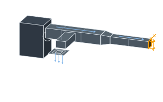
The total length of the flex duct run.
The developed length AS INSTALLED — including the sag between supports and whatever surplus was left in rather than cut off. Flexible duct is routinely fitted longer than the distance it has to cover, because cutting it takes a moment and leaving it does not, and every bit of that surplus is pure resistance. Measuring the straight-line distance instead understates the loss on exactly the installations that have the most of it.
How much higher the flex duct's actual friction runs versus smooth rigid duct, based on how well it's installed.
A fully-extended flex duct runs roughly 1.5-3x smooth duct friction; a typical field installation with some sag or compression can run 3-4x or considerably higher if compressed or kinked. Use the specific product's manufacturer chart when it's available.
Estimated total friction pressure loss
0.059 in. w.g.
This uses a third-party curve-fit approximation of the ASHRAE Fundamentals duct friction chart, not an ASHRAE-published closed-form equation, plus a user-supplied installation-quality multiplier standing in for the actual flex-duct friction chart. For final duct design, use the specific flex duct manufacturer's published friction chart (required by ACCA Manual D Appendix 3) rather than this screening estimate — a compressed or sagging flex run can have far higher friction than the multiplier ranges shown here suggest.
- Base smooth-duct friction rate (per 100 ft)
- 0.04 in. w.g./100 ft
They open the calculator with your figures already in it
Flexible Duct Friction Pressure Loss Calculator: 0.0595 in. w.g. — shown in imperial, US market. The link sets both, so the result they see is the one on your screen.
Show calculation logicHide calculation logic
How this was calculated
Formula source(s)
- Base friction rate (in. w.g. per 100 ft) = 0.109136 × CFM^1.9 ÷ Diameter(in)^5.02, a widely-reproduced curve-fit approximation of the ASHRAE Fundamentals Ch. 21 smooth round galvanized duct friction chart. Flexible duct has significantly higher friction than smooth rigid duct of the same diameter — per ASHRAE-sponsored research (Culp, 'Compression Effects on Pressure Loss in Flexible HVAC Ducts'), a fully-extended flex duct runs roughly 1.5-3x smooth duct friction, while typical field installations with some sag/compression can run 3-4x or considerably higher; ACCA Manual D Appendix 3 and manufacturer-published flex-duct friction charts are the authoritative source for a specific product.
Inputs used
- Airflow
- 150 CFM
- Duct Diameter
- 8 in
- Duct Run Length
- 39 ft
- Installation-Quality Friction Multiplier (1.5-2 Fully Extended, 3-4 Average Sag, 5-10+ Compressed/Kinked)
- 3.5
Intermediate steps
- Base smooth-duct friction rate (per 100 ft)
- 0.04 in. w.g./100 ft
Confidence note: This uses a third-party curve-fit approximation of the ASHRAE Fundamentals duct friction chart, not an ASHRAE-published closed-form equation, plus a user-supplied installation-quality multiplier standing in for the actual flex-duct friction chart. For final duct design, use the specific flex duct manufacturer's published friction chart (required by ACCA Manual D Appendix 3) rather than this screening estimate — a compressed or sagging flex run can have far higher friction than the multiplier ranges shown here suggest.
What this calculation does not cover
- Fittings are not in this run. The number covers straight duct only, and on a flex branch the elbows, the boot at the ceiling, the takeoff collar at the trunk and the balancing damper are usually worth more pressure than the straight length is. Manual D handles them as equivalent length, and a single tight-radius bend in flex can be worth tens of feet of straight duct on its own — add those equivalent lengths into the run length above before treating this as the branch's loss.
- One branch is not the system. What the blower has to overcome is the whole path — return grille, filter, coil, supply trunk, this branch and the register at the end — and the fan's available external static is what all of it shares. A branch that reads a comfortable 0.06 in. w.g. can still be the one that starves, because the coil and the trunk ahead of it already spent the budget.
Add the equipment this sizes
This result is a specification — 0.059 in. w.g. — not a quantity. Put the thing it sizes into your project: how many, what you call it, and your supplier’s price.
Computed in your browser — nothing you enter is uploaded. Presented in US customary units and US trade terminology. Where a formula follows a published standard, that standard and its edition are cited beside it on this page; where none governs, the page says so. Local amendments override model codes — verify against the code in force where you build.
Sources checked 2026-09-06 · in the site-wide review of 2026-09-06 · v1.0.1
Regulatory standards & verification citations1
- Base friction rate (in. w.g. per 100 ft) = 0.109136 × CFM^1.9 ÷ Diameter(in)^5.02, a widely-reproduced curve-fit approximation of the ASHRAE Fundamentals Ch. 21 smooth round galvanized duct friction chart. Flexible duct has significantly higher friction than smooth rigid duct of the same diameter — per ASHRAE-sponsored research (Culp, 'Compression Effects on Pressure Loss in Flexible HVAC Ducts'), a fully-extended flex duct runs roughly 1.5-3x smooth duct friction, while typical field installations with some sag/compression can run 3-4x or considerably higher; ACCA Manual D Appendix 3 and manufacturer-published flex-duct friction charts are the authoritative source for a specific product.
Which documents these citations point at
Standards referenced: ACCA Manual D (Air Conditioning Contractors of America, United States).
Cite this page
Your workspace
Most jobs need more than one number. Add the calculators you need next and they open right here, underneath this one — your figures stay on screen and nothing is lost to a page change.