
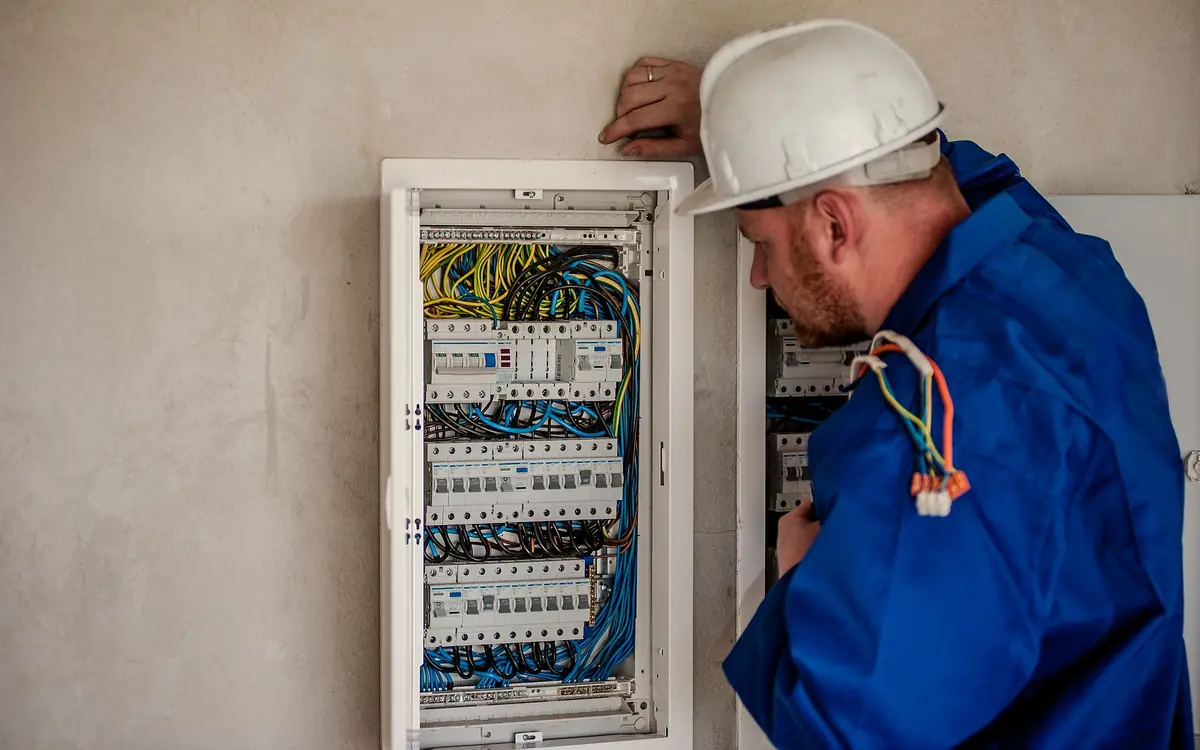
Forty-one fittings, and the fourth one was hollow
The commissioning walk at a solvent day-tank building came apart over a screwdriver. Forty-one sealing fittings on the electrical drawing, every one installed, threaded up hard, painted the same grey as the rack they were bolted to. The inspector took the filling plug out of the fourth one, slid a long blade in, and it went the full depth of the bore without touching anything but conductor insulation and air. He then opened nine more. Six were empty. The building had been electrically complete for five months.
Nothing about the outside of a sealing fitting tells you whether it was ever filled. The body goes in with the pipe, at rough-in, usually by whoever is threading conduit that week. The compound cannot go in until the conductors are pulled, dressed and separated, which is a different visit, sometimes a different subcontractor, and always after the part of the job that anyone is watching. A seal is the one component on a hazardous-area installation that is installed twice and inspected once, and the second installation is the one that does the work.
It helps to be blunt about what that second visit is for. The compound in a seal-off is not weatherproofing, not a strain relief, not a moisture barrier and not a way of tidying an entry. It is a plug that stops a flame front travelling along the inside of a pipe, and it stops pressure travelling with it. Everything else on this page — where the fitting is permitted to sit, how many conductors may pass through it, how deep the compound has to be, what order the work happens in — follows from that single job.
What a flame front does once it is inside a pipe
An explosionproof enclosure does not keep the atmosphere out. It expects the surrounding gas or vapour to get in, expects an internal component to ignite it eventually, and is built to survive that. Its joints are machined flame paths: a defined gap over a defined length, so the burning products forced out of the box are cooled below the ignition temperature of the mixture outside before they clear the joint. That is the whole trick, and it is tested rather than calculated — UL 1203, Explosion-Proof and Dust-Ignition-Proof Electrical Equipment for Use in Hazardous (Classified) Locations, in North America, and IEC 60079-1, Equipment protection by flameproof enclosures 'd', for Ex d equipment elsewhere.
Gas grouping exists because that quenching gap is not the same for every substance. The NEC's Groups A through D and the IEC's IIA, IIB and IIC sort atmospheres by how narrow a slot will still let a flame through, which is measured as the maximum experimental safe gap. Hydrogen and acetylene sit at the demanding end; that is why a Group IIC or Group B enclosure is a heavier casting with longer flanges than a Group IIA or Group D one. It is also why nothing on this subject generalises: the group on the classification drawing is part of the specification of every fitting on the run.
Now put a threaded conduit into the side of that enclosure. It is a smooth, straight bore, orders of magnitude wider than the gap the machined joints hold to, with nothing anywhere along it to quench a flame, and it is full of the surrounding atmosphere because a conduit system breathes — it warms, it cools, it draws in whatever the room is holding. An internal ignition that the enclosure itself would have survived now has a clean route out of it, along the pipe, into the next enclosure or into a room the classification drawing says should never see a flame. The enclosure did its job and the pipe undid it.
The more expensive failure is pressure piling. When the flame front runs down a connected volume, it drives the unburnt mixture ahead of it and compresses it. The charge waiting in the second enclosure ignites from a pre-compressed starting pressure, so the pressure rise it produces is a multiple of what the casting was hydrostatically tested against. Enclosures split at bolt lines rather than at flame paths when this happens. A seal breaks the connected volume into pieces small enough that this cannot build, which is why the code cares where the fitting sits and not merely that one exists.
What is inside the chamber, bottom to top
The fitting body is the only part chosen from a catalogue. It has to be listed for the class, group and division it sits in — a fitting good for Class I Group D is not automatically good for Group B — and it goes on to threaded rigid metal conduit or threaded steel intermediate metal conduit with the five fully engaged threads that NEC 500.8(E) asks of threaded joints in explosionproof systems. Tapered thread cut short, or made up with a pipe wrench onto two threads because the run came up long, is a defect in the flame path before the compound is even mixed.
The two things poured into it do different jobs and get confused constantly. The fibre dam is packing: loose mineral fibre worked into the bore and, critically, between and around every individual conductor, so that the compound poured on top of it stops where it is meant to stop. It is not the seal. The compound is the seal, and it is a mineral powder mixed with water to a heavy cream, poured, and left to set hard against the bore wall and against each conductor's insulation. If the dam was packed around the outside of a taped bundle rather than between the conductors, the compound sets around a bundle too, and the flame path runs through the interstices between the cables. The fitting will look, weigh and sound exactly like a good one.
What a poured seal-off is made of
- Filling plug — the last thing closed and the only thing an inspector can open, which makes it the only evidence from outside that the chamber below it was ever filled
- Poured sealing compound — the actual plug in the flame path, set hard against the bore and against each conductor — its depth, not its presence, is what the code puts a number on Explosion-Proof Seal-Off Compound Volume Calculator
- Fibre dam — packed between and around every individual conductor so the compound sets around each one rather than around a taped bundle with gaps inside it
- Conductors through the chamber — held to a quarter of the equivalent conduit's cross-section, which is far less than the same trade size of pipe is allowed to carry on its own Conduit Fill Calculator
- Fitting body on the conduit — listed for the class, group and division of the area around it, and made up to full thread engagement on rigid or threaded steel intermediate conduit
- The enclosure being protected — the arcing device whose 450 mm the fitting has to sit inside, and the volume an unsealed conduit would otherwise charge with pre-compressed mixture
Where the fitting is allowed to sit
Article 501.15 of NFPA 70, the National Electrical Code, asks for seals in two quite different situations, and treating them as one rule is where most field arguments start. One protects an enclosure. The other protects a boundary. They have different distances, different lists of what may sit between the seal and the thing it is protecting, and different consequences when they are wrong.
The enclosure seal is the tight one. In a Class I Division 1 location a conduit seal goes within 450 mm — 18 inches — of any enclosure containing arcing or sparking parts, and within the same distance where trade size 2 conduit or larger enters an enclosure holding terminals, splices or taps. Between that fitting and the enclosure the code permits only explosionproof unions, couplings, reducers, elbows and capped elbows no larger than the trade size of the conduit. No condulet, no box, no length of flexible connection, and no run of pipe long enough to be convenient. A single seal is permitted to serve two enclosures joined by a nipple or a short run of conduit — not more than 900 mm, 36 inches — provided it sits within 450 mm of each of them, which is worth designing for on a pair of devices mounted close together.
The boundary seal is the loose one, and it is the one people forget entirely. Where a conduit leaves a classified location for an unclassified one, the classification does not stop at the wall — the pipe carries the atmosphere across with it. The seal may sit on either side of the boundary within 3.05 m, ten feet, and the run between the seal and the point at which the conduit crosses out must contain no union, coupling, box or fitting other than listed explosionproof reducers at the conduit entry. That last clause is the one that catches retrofits: someone adds a coupling to extend a run and turns a compliant boundary seal into a non-compliant one without touching the seal at all.
There are markings and there are exceptions, and both are worth reading rather than remembering. Equipment marked to indicate that a seal is not required at its entries has been tested that way and its nameplate is the listing speaking; a factory-sealed device does not get a second seal because someone liked the look of it. The edition of the code in force also carries exceptions for runs that pass straight through a Division 2 area and for boundaries into outdoor unclassified space, and those move between editions and local amendments. Take them off the adopted edition on this job, not off the one you learned the trade on.
| What is being protected | Where the fitting goes | What may sit between it and the thing it protects |
|---|---|---|
| A Class I Division 1 enclosure containing arcing or sparking parts | Within 450 mm (18 in) of the enclosure | Explosionproof unions, couplings, reducers, elbows and capped elbows no larger than the conduit trade size |
| A Class I Division 1 enclosure holding terminals, splices or taps, entered by trade size 2 conduit or larger | Within 450 mm (18 in) of the enclosure | The same short list, and nothing outside it |
| Two enclosures joined by a nipple or a run of conduit no longer than 900 mm (36 in) | One fitting in that run, within 450 mm (18 in) of each enclosure | The connecting nipple or conduit and the fittings above |
| The boundary where conduit leaves a classified location | Either side of the boundary, within 3.05 m (10 ft) | Listed explosionproof reducers at the conduit entry only — no union, coupling, box or other fitting |
| An entry on equipment marked to say no seal is required | No fitting at that entry | Read the nameplate rather than the catalogue page, and record which device it was |
The fill limit that chooses the fitting, not the conduit
Article 501.15 puts its own limit on how full a sealing fitting may be: conductor fill in the fitting must not exceed 25 percent of the cross-sectional area of a rigid metal conduit of the same trade size, unless the fitting is specifically listed for a higher percentage. That is a limit on the fitting, and it is not the limit that sized the pipe.
The conduit itself was sized against Chapter 9, Table 1 of the same code, which allows 40 percent for three or more conductors. So a run that was drawn at, and is legitimately at, 40 percent will not pass through a seal fitting of the same trade size. The arithmetic is not close: the fitting is being asked to carry a bit over half of what the pipe feeding it holds. On a hazardous-area schedule this shows up either as an upsized sealing fitting with explosionproof reducers either side of it, or as circuits split across more conduits than the unclassified version of the same design would have used, and both cost money that has to be in the estimate rather than discovered at second fix.
There is a second, softer reason to be under the number rather than at it. The dam has to be worked between individual conductors by hand, through a filling opening a good deal smaller than the bore. A chamber packed to its theoretical limit is a chamber where the fibre goes around the outside of the bundle because that is the only place a thumb will reach, and that is precisely the seal that looks right and passes nothing. Size the fitting so the conductors can be spread across the bore with daylight between them, then dam it.
Run the conductor bundle against the pipe first. What comes back is the count the conduit itself will take at 40 percent; the fitting beside it is held to 25, so a little under two thirds of that count is what the seal of the same trade size will pass — and the gap between the two numbers is what says whether it has to be a size up.
The gauge of the conductors being pulled through the conduit.
The trade size of the EMT conduit.
Maximum conductors
16 conductors (maximum)
This uses standard EMT and THHN area tables — different conduit types (PVC, rigid) or conductor insulation types have different area values. Always verify against the current NEC Chapter 9 tables for your specific materials.
- Available fill area (40% of conduit)
- 0.21 in²
They open the calculator with your figures already in it
Conduit Fill Calculator: 16 conductors (maximum) — shown in imperial, US market. The link sets both, so the result they see is the one on your screen.
What this calculation does not cover
- Fill is not ampacity. This says how many conductors physically fit under the 40% rule; it does not derate them, and the NEC requires conductor ampacity to be adjusted downward once more than three current-carrying conductors share a raceway. A bundle that passes fill can still need a larger conductor or a smaller breaker — this is not a load calculation and it does not size the circuit.
- EMT and THHN/THWN only. PVC, IMC, rigid and flexible raceways have different internal areas at the same trade size, and other insulations — XHHW, TW, RHW, anything with a thicker jacket — have different conductor areas. Change either and the count changes.
- Every conductor in the raceway counts toward the 40%, including neutrals and the equipment grounding conductor, and the count assumes they are all the same size. A bundle mixing gauges has to be totalled area by area against 40% of the conduit's internal area rather than read off a single-gauge count.
- Fitting is not pulling. Nothing here accounts for run length, the number and radius of bends, pulling tension, lubricant or conductor jamming — a conduit loaded to the code maximum across a long run with several bends can be impractical to pull.
- These are US NEC figures for a run of three or more conductors. A single-conductor run is permitted 53% fill and a short nipple between enclosures 60%, but a two-conductor run is held to 31% — less than the 40% applied here, not more. Outside North America conduit is sized by different methods entirely, so check the code edition and any local amendments your jurisdiction has adopted.
Laying the run out so you can still reach the plugs
A seal schedule is a layout exercise, not a materials one, and it belongs on the drawing at the same time as the enclosures. Mark every fitting, number it, and walk the route in your head asking one question at each mark: on the day the compound is poured, can somebody get a hand, a funnel and a torch to that filling opening? A seal that ends up under grating, behind a vessel skirt, or tight above a pipe rack is a seal that will be reported as poured and will not be.
Orientation is a listing matter, not a preference. Sealing fittings are listed for the positions they were tested in — some for vertical use only, some for vertical or horizontal — and the filling opening has to sit above the level the compound will reach, or the compound leaves through it. Reading the fitting's own instruction sheet before the pipe is bent is a five-minute job; discovering at the pour that a fitting was installed upside down means cutting it out of a threaded run.
Water is the other layout constraint, and it is the one the opening premise of this page turns on. Compound does not hold water back; it is not asked to. Article 501.15 handles trapped liquid and condensed vapour separately, through drainage provisions and through drain-type sealing fittings with an integral explosionproof drain. Arrange the run so it falls away from the seals rather than into them, because a seal at the low point of a vertical drop becomes the bottom of a bathtub, and the water sitting on it goes into the enclosure the moment somebody opens the cover.
Then there are the bends. Rigid conduit is limited to 360 degrees of bend between pull points, and a sealing fitting is not a pull point — it is not a box, and the code prohibits splices and taps in a fitting intended only for sealing. Count the run through its bends as a single continuous pull from box to box, with the seals as obstacles inside it rather than as places to rest. The developed length that comes out of that count is what goes on the material order and what feeds the pull calculation in the next section.
Developed length through the bends is what makes a hazardous-area run different to price and different to pull, because the seals sitting inside it are obstacles rather than the pull points a normal run would break at. The arc arithmetic is the pipe's geometry rather than its material, so it reads the same for threaded rigid as for the EMT it is named after — take the bend radius off the shoe you are actually bending with.
The sum of all the straight conduit segments in the run, not counting the bends.
The total number of 90-degree bends in the conduit run.
The centerline bend radius used for each 90-degree bend.
Total conduit length needed
68.36 ft
- Arc length per bend
- 0.79 ft
They open the calculator with your figures already in it
EMT Conduit Bend Length Calculator: 68.36 ft — shown in imperial, US market. The link sets both, so the result they see is the one on your screen.
Estimated cost — your price
This site holds no price list for this material — local prices vary too much to publish honestly. Enter your supplier's price and the result is costed with it.
What this calculation does not cover
- This is the length of pipe to buy, not where to mark it. A bender's take-up — the distance from the end of the stub back to the mark, about 5 in (127 mm) for 1/2 in EMT and rising with size — is what puts a 90 in the right place, and the arc length here is a different figure entirely. Use this for material and the bender's take-up for the layout, or every stub finishes at the wrong height.
- The bend count is not tested against the pull. A run is limited to 360 degrees of bend between pull points, which is four 90s and no more, and this page will happily total twenty of them. Past the limit the run either will not pull at all or the conductors get dragged through hard enough to damage the insulation, and the fix is a pull box that was never in the estimate.
- Only 90° bends are counted. Offsets, kicks, saddles and 45s each add developed length over the straight line they replace, so a run threaded around ductwork with a dozen offsets in it consumes noticeably more pipe than a straight-run-plus-90s total — allow for those separately or the last stick lands short.
One pull, one pour, and no second go at either
Set compound is the end of that conduit's working life as a route. You cannot add a conductor through a poured seal, you cannot pull one out, and you cannot drill the compound and claim the seal survived. Adding a circuit later means cutting the fitting body out of a threaded run and starting again. So before anybody mixes anything, the question on the table is not 'are the conductors in' but 'is everything that will ever be in this pipe in it' — including spare conductors, which have to be pulled now, and spare conduits, which still need their own seals whether they carry anything or not.
The pull leaves residue behind it, and the compound has to bond to what it finds. Wipe pulling lubricant off every conductor inside the chamber before the fibre goes in; compound poured onto a greased jacket sets around it rather than to it. Temperature matters at both ends of the day — mixed compound has a working life measured in minutes rather than hours, and a mineral compound mixed with water and left to freeze before it sets is scrap. Mix to the ratio on the container, mix what you will pour, and pour it immediately.
This is why the pull plan for a hazardous-area run deserves more attention than the same run in an unclassified building. In an ordinary conduit a pull that jams can be backed out, re-lubricated and tried again with no consequence beyond an afternoon. Here, a conductor damaged on a bend and not noticed becomes a fault behind a set seal, and the repair is a fitting replacement in a live plant with a hot-work permit attached to it. Work the tension out before the rope goes on, knowing that a straight-run figure is a floor rather than an answer — every bend multiplies whatever has built up ahead of it, and the pressure the cable puts on the inside of that bend is a separate check with a limit of its own — and treat what comes back as the reason to add a pull point rather than as a number to argue with.
- Confirm every conductor and every spare that run will ever carry is pulled, and that the tails inside the chamber are long enough to separate.
- Wipe pulling lubricant and swarf off the conductors where the compound will sit.
- Spread the conductors across the bore so none of them is touching another.
- Pack the fibre dam between and around each conductor, filling the annulus to the depth the fitting's instruction sheet gives.
- Mix the compound to the water ratio on the container, in the quantity you are about to pour and no more.
- Pour until the compound depth over the dam meets the code minimum — not less than the trade size of the fitting, and never less than 16 mm (5/8 in).
- Refit the plug to full thread engagement, using only a thread compound the fitting's listing permits.
- Mark the fitting, sign it off against its number on the seal schedule, and photograph it.
Worth knowing before the rope goes on here rather than after, because a conductor damaged on a bend and discovered later sits behind compound that has already set. It returns the straight-run figure only — a floor to design against on a run whose bends will multiply it, and not the sidewall pressure at those bends, which is checked separately against the cable maker's limit.
The cable's weight per unit length, including its jacket and any armor.
The total length of the straight conduit run being pulled.
The friction between the cable jacket and the conduit interior.
Estimated pulling tension
67 lbf
This covers a STRAIGHT run only — pulls with bends require adding capstan-equation tension multipliers for each bend, and the calculated tension must be checked against the cable manufacturer's maximum allowable pulling tension (often based on conductor cross-section) before pulling. Consult a qualified installer for multi-bend or long/complex pulls.
- Tension in kgf
- 30.18 kgf
They open the calculator with your figures already in it
Cable Pulling Tension Calculator (Straight Run): 66.52 lbf — shown in imperial, US market. The link sets both, so the result they see is the one on your screen.
Add the equipment this sizes
This result is a specification — 67 lbf — not a quantity. Put the thing it sizes into your project: how many, what you call it, and your supplier’s price.
What this calculation does not cover
- Jamming and clearance are failure modes that are not forces, so no tension figure predicts them. Three cables of similar diameter can wedge side by side going through a bend when the conduit's inside diameter falls in a narrow band near three times the cable diameter, and the pull locks solid at a tension the winch will happily exceed and the cable will not survive. A single large conductor has the mirror problem — it needs a minimum clearance to the conduit wall through every bend. Check the geometry of what is going in before trusting any number here.
- Cold changes the pull and can end it. Jacket and insulation stiffen as the temperature drops, so the same cable in the same conduit pulls appreciably harder in winter than the friction coefficient above suggests, and most cables carry a minimum installation temperature below which the jacket cracks rather than bends. Neither the friction figure nor the weight in this calculation moves with temperature; warming the reel before the pull does more than either of them.
- This is what the conduit costs you. The reel adds its own before the cable reaches the conduit at all — a heavy drum with a stiff brake, a feed that is not squared up with the conduit mouth, or a sheave set at the wrong angle each contribute back-tension and an extra effective bend right at the head of the run, and being at the head, everything downstream multiplies it.
Buying compound for forty-one seals
The depth of the compound is a code number, not a judgement. In a completed seal the compound thickness must be at least the trade size of the sealing fitting, and in no case less than 16 mm — five-eighths of an inch. So the volume in any one fitting is the bore area multiplied by a depth you are not free to shave, and that fixes it as an order quantity rather than something to top up out of what is left in the bucket at the end of a level.
Two honest limits on the arithmetic. The bore volume is the empty-chamber figure: the conductors passing through displace part of it, so the real quantity is less, by an amount that depends on how much cable is in there. And the manufacturer's own fill table for that catalogue number is the authority for any individual fitting — Eaton Crouse-Hinds publishes one for Chico A compound against each seal type, and the competing lines publish their own. Use a calculated volume for the ORDER, across a schedule of forty-one fittings where the difference between a plausible number and a guess is several cans, and use the instruction sheet at the fitting.
One property is worth checking on the container rather than assuming. Article 501.15 requires the compound to seal against passage of gas or vapour, to be unaffected by the surrounding atmosphere or liquids, and to have a melting point of not less than 93 degrees Celsius — 200 degrees Fahrenheit. That rules out most of what is on a general electrical van: duct seal, silicone, expanding foam and ordinary grout are all wrong here, and two of them will pass a casual glance through the filling opening. Buy the compound the fitting is listed with, and mix only what the next few fittings will take, because a can gone off in the back of a van is cheaper to replace than to explain.
Bore diameter and chamber length give the empty-chamber volume, which is what a purchase order needs across a whole seal schedule — the conductors inside will take a share of it, and the fitting's own fill table settles any single pour.
The inside diameter of the seal-off fitting's bore.
The length of the fitting's sealing chamber to be filled with compound.
Sealing compound volume needed
0.0068 gal
This assumes the full bore is open (no conductors inside) — conductors occupy some volume, reducing the actual compound needed, but per NEC 501.15 and the sealing compound manufacturer's instructions, the minimum compound thickness and fill requirements must still be verified against the actual conductor fill in your specific fitting.
They open the calculator with your figures already in it
Explosion-Proof Seal-Off Compound Volume Calculator: 0.0068 gal — shown in imperial, US market. The link sets both, so the result they see is the one on your screen.
Estimated cost — your price
This site holds no price list for this material — local prices vary too much to publish honestly. Enter your supplier's price and the result is costed with it.
What this calculation does not cover
- The chamber does not get filled with compound alone. A fiber dam is packed in first to hold the compound while it sets, and it occupies part of the very cavity this figure measures — so the pourable volume sits below the number above for a reason that has nothing to do with the conductors, and how far below depends on how much fiber the fitting and the conductor bundle need.
- One fitting. What actually drives the compound order on a hazardous-location job is how many seals the installation needs, and NEC 501.15 sets that by location rather than by volume: a seal within 18 in (457 mm) of each enclosure containing an arcing device, and seals where the raceway crosses out of the classified area. Take the seal count off the drawings and run this page once per fitting size.
- Sealing compound is not poured out of a tub in whatever amount a fitting needs. It comes in pre-portioned packs mixed with a fixed amount of water and it stiffens within minutes, so this volume has to be rounded up to whole packs, a part-used mix is thrown away, and one pack cannot be stretched across two fittings unless they are close enough to pour back to back.
Dust is a different problem wearing the same fitting name
Class II locations — combustible dust — use the word 'seal' for a job that is not the same job. Article 502.15 is about keeping dust out of the raceway and out of the enclosure at the other end of it, rather than about arresting a flame front in a bore, and the difference shows in what it will accept: alongside a compound-filled fitting it recognises lengths of raceway themselves as a seal, horizontal or vertical, and it does not require the seal to be explosionproof. A crew that installs a Class I fitting and pours it in a Class II location has done more than was asked; a crew that reasons the other way round has done a great deal less.
What does carry across is the classification discipline. The area drawing that names the class, division or zone, the group, and the temperature class comes from a study — NFPA 497 for flammable gases and vapours in chemical process areas, NFPA 499 for combustible dusts, API RP 500 and API RP 505 for petroleum facilities — and it is a document with an author and a revision, not a judgement made on the walk-round. Dust brings its own governing figure in the form of the layer and cloud ignition temperatures that set the equipment's T-code, which is a different constraint from the gas group but arrives from the same drawing. Read it before choosing a single fitting.
The same job outside the Division system
Half the world classifies by zone rather than by division and reaches the same requirement by a different route. Under IEC 60079-14, Electrical installations design, selection and erection, the conduit systems that do exist are required to carry sealing devices at the entry to flameproof enclosures and where a conduit crosses out of a hazardous area, on the same logic that Article 501.15 uses: break the connected volume, and stop the flame path where the classification changes. Article 505 of the NEC and API RP 505 provide the zone vocabulary inside North America, CSA C22.1 Section 18 does it in Canada, and AS/NZS 60079.14 in Australia and New Zealand.
The bigger practical difference is that conduit is uncommon in IEC practice at all. Cable with a certified gland is the norm, and the equivalent of a poured seal there is the barrier gland: a compound-filled or resin-filled gland, certified as an assembly, whose barrier is made up on site with a two-part compound to the gland maker's instructions. It fails the same way seal-offs do — unfilled, or filled around the outside of a bundle instead of between the cores — and it is inspected for the same reason. NEC 501.15 covers the parallel cable cases in Divisions 1 and 2 for anyone working to the American code with cable rather than pipe. Wherever the job sits, the duty behind it is statutory: DSEAR in Great Britain, with its Approved Code of Practice, and the ATEX workplace directive across the EU.
Proving, later, that a seal was ever poured
Nothing in Article 501.15 tells you to mark a poured seal. That is trade discipline rather than code, and it is worth adopting anyway, because the alternative is the afternoon this page opened with. Number every fitting on the drawing, tick it off in a seal schedule when the compound goes in, sign the line, and photograph the open chamber with the compound visible before the plug goes back. A painted plug or a stamped tag gives an inspector something to sample against rather than a reason to open all forty-one.
That record is also the thing that survives the crew. Hazardous-area installations are subject to a periodic inspection regime — IEC 60079-17, Explosive atmospheres, electrical installations inspection and maintenance, sets out initial, periodic and sample inspection in the IEC world, and the equivalent duty sits with the operator everywhere else. An inspector arriving in year four with a seal schedule can verify a sample and move on. An inspector arriving with no schedule has to treat every fitting as unknown, and the cost of that lands on the operator rather than on whoever saved an hour not writing it down.
The last thing to hand over is the constraint itself, in writing. Every future modification to a sealed run reopens the question this page answers: a conductor added, a device swapped for one whose nameplate no longer says the seal is not required, a coupling installed on the wrong side of a boundary seal, a fitting relocated more than 450 mm from the enclosure it protects. Those are the changes a maintenance team makes in an afternoon without knowing what they were touching. A drawing that marks the classified boundary and the seals on it is what stops that, and it is cheaper than the alternative by several orders of magnitude.
Before anybody mixes compound
What has to be settled at the fitting, seeded with a bore and chamber in the range a trade size 1 seal occupies — replace both with the figures off the fitting's own instruction sheet.
- The area classification drawing, by revision — Class or zone, division, gas or dust group and temperature class. Every fitting on the run is specified from this sheet, and it has an author and a date.
- A numbered seal schedule on the electrical drawing — One line per fitting, marked as enclosure seal or boundary seal, so the 450 mm and the 3.05 m rules are checked on paper rather than argued about on the rack.
- Fitting size checked against the 25 percent conductor fill — The pipe was sized at 40 percent. A seal of the same trade size will not take that bundle, and the upsize plus reducers belongs in the estimate.
- Filling openings reachable, and above the compound line — Orientation is part of the listing. Walk the route asking whether a hand, a funnel and a torch reach every plug on pour day.
- Compound listed with the fitting, in dated cans — Melting point not below 93 °C (200 °F), mixed to the ratio on the container, in the quantity about to be poured. Duct seal, silicone and foam are all wrong.
- A signed line and a photograph per seal — The only thing that distinguishes a poured fitting from an empty one after the plug goes back, and the only thing an inspector can sample instead of opening all of them.
Opens the calculators above on one screen with the dimensions from this article already filled in. Quantities only — this site publishes no price list, because local prices vary too much to publish honestly.