
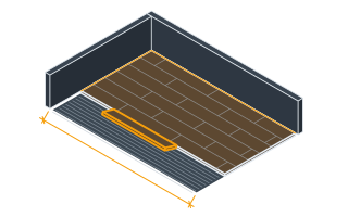
SettingsSettings for this calculationUS
The length of the raised access floor area.
Measure the full extent of the raised floor along one axis.
The width of the raised access floor area.
Measure the full extent of the raised floor along the perpendicular axis.
The center-to-center spacing of the pedestal grid, matching the access floor panel size.
600 mm (24 in) is the standard panel grid spacing for raised access floor systems.
Stringer bars needed
472 stringers
- Pedestals along length
- 18
- Pedestals along width
- 14
- Short bay at the wall, along the room
- 1 ft
- Short bay at the wall, across the room
- 0 ft
They open the calculator with your figures already in it
Raised Access Floor Stringer Bar Calculator: 472 stringers — shown in imperial, US market. The link sets both, so the result they see is the one on your screen.
Show calculation logicHide calculation logic
How this was calculated
Formula source(s)
- In a stringer-braced access floor grid, connecting bars run between every adjacent pair of pedestals in both directions: horizontal connections = (pedestals along length − 1) × pedestals along width; vertical connections = pedestals along length × (pedestals along width − 1)
Inputs used
- Room Length
- 33 ft
- Room Width
- 26 ft
- Panel Grid Spacing (Standard 0.6m/24in)
- 2 ft
Intermediate steps
- Pedestals along length
- 18
- Pedestals along width
- 14
- Short bay at the wall, along the room
- 1 ft
- Short bay at the wall, across the room
- 0 ft
What this calculation does not cover
- Counts bars, and says nothing about which bar. Understructure load rating — concentrated load, ultimate load, and the rolling load a wheeled cart imposes — belongs to the panel and stringer as a matched assembly, and a data hall grid takes a heavier gauge stringer at exactly the count returned here. The right number of the wrong bar shows up as deflection under a loaded rack cart, never on the packing list.
- The grid is assumed to land on whole modules with nothing in the way. Any room dimension that is not a multiple of the grid spacing leaves a short bay at the wall, which needs a cut-to-length bar or a perimeter support angle rather than a standard stringer — while every column, duct penetration, floor box and ramp deletes bays this rectangle still counts. The two errors run in opposite directions and do not cancel.
- Lateral stability is not a bar count. Above roughly 600 mm (24 in) of free height, and in any seismic design category that calls for it, the understructure needs bolted stringers, braced pedestal lines and base plates anchored to the slab — added hardware and a different pedestal, not more of the same stringer.
Estimated cost — your price
This site holds no price list for this material — local prices vary too much to publish honestly. Enter your supplier's price and the result is costed with it.
Computed in your browser — nothing you enter is uploaded. Presented in US customary units and US trade terminology. Where a formula follows a published standard, that standard and its edition are cited beside it on this page; where none governs, the page says so. Local amendments override model codes — verify against the code in force where you build.
Sources checked 2026-09-06 · in the site-wide review of 2026-09-06 · v1.0.1
Regulatory standards & verification citations1
- In a stringer-braced access floor grid, connecting bars run between every adjacent pair of pedestals in both directions: horizontal connections = (pedestals along length − 1) × pedestals along width; vertical connections = pedestals along length × (pedestals along width − 1)
Cite this page
Your workspace
Most jobs need more than one number. Add the calculators you need next and they open right here, underneath this one — your figures stay on screen and nothing is lost to a page change.