
SettingsSettings for this calculationUS
The area the load presents to the wind, seen along the wind direction.
Take the worst orientation the load can end up in, not the one it starts in — a panel that begins edge-on will find its broad face if it is allowed to rotate. Sheeted scaffolding, formwork panels, cladding units and empty tanks are all large-area, low-weight items, and those are the loads wind hurts people with.
The gust speed at the height the load will actually hang, not the average at ground level.
Gusts break lifts, not averages, and wind rises with height — the reading beside the site cabin can be a fraction of what the boom tip sees. Anemometer readings at the tip are the figure that counts, and every crane has a maximum permissible wind speed printed for its configuration.
Tools needed: Anemometer, ideally boom-tip mounted, Manufacturer's wind limit for the configuration
The drag coefficient for the load's shape, from the standard governing the lift plan.
A compact, rounded object sheds wind; a flat panel does not, and a lattice or sheeted frame behaves differently again depending on how solid it is. The value dominates the answer as directly as the area does, so lifting it from a general figure to the right one for a flat panel can change the force by half as much again.
The density of the air the lift takes place in.
The default is the standard atmosphere at sea level in mild conditions. Cold air is denser and pushes harder for the same wind speed, while altitude thins it — a lift on a cold morning at sea level sees a noticeably larger force than the same lift on a hot afternoon on a plateau.
The weight of the item hanging below the hook.
Weight is what resists the swing, which is why light loads with large faces are the dangerous ones. The same gust that barely disturbs a dense casting will push a sheeted panel of the same area a long way off vertical.
The length of hoist rope between the boom head and the load.
The load swings on this length like a pendulum, so the same angle produces a far larger offset on a long fall than on a short one. Keeping the load high and the fall short is one of the few field measures that genuinely reduces wind-driven swing.
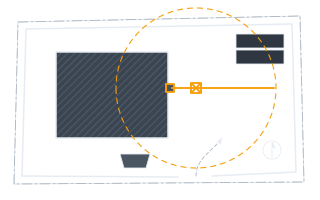
The horizontal distance from the crane's centre of rotation to the load.
Used to express the wind's effect as a moment, which is the language a capacity chart speaks. A given force matters far more at a long radius than a short one, and the radius itself grows when the load swings outward.
Horizontal wind force on the load
798 lbf
A static description of one gust on one orientation. It does not model the load swinging, rotating into its worst face, or the wind acting on the boom and the crane itself, all of which the manufacturer's permissible wind speed already accounts for — that limit governs, not this arithmetic.
- Wind pressure on the sail area
- 6.14 lbf/ft²
- Angle the load hangs off vertical
- 6.88 °
- Sideways offset of the load
- 3.95 ft
- Added moment from the offset
- 26.15 kip·ft
- Moment about the slew centre if the wind blows across the boom
- 52.68 kip·ft
- Load moment at the radius with no wind
- 436.59 kip·ft
They open the calculator with your figures already in it
Suspended Load Wind Force and Swing Calculator: 798 lbf — shown in imperial, US market. The link sets both, so the result they see is the one on your screen.
Show calculation logicHide calculation logic
How this was calculated
Formula source(s)
- Wind force = ½ × air density × wind speed² × shape factor × projected sail area, the standard dynamic-pressure form used for wind loading on a body
- Air density default of 1.225 kg/m³ is the International Standard Atmosphere value at sea level and 15 °C; cold, dense air produces a larger force at the same wind speed
- RULE OF THUMB, stated as one: the default shape factor of 1.2 is a general value for a compact load. Flat plates, panels and lattice frames all differ, sometimes substantially, and the governing coefficient comes from the standard the lift plan is written under or from the crane manufacturer's own guidance
- Swing geometry: a suspended load hangs at the angle whose tangent is the horizontal force divided by the load's weight, and the offset at the load is the rope length below the boom head times the sine of that angle
Inputs used
- Projected Sail Area of the Load
- 130 sq ft
- Gust Wind Speed at Boom-Tip Height
- 65.62 ft/s
- Shape (Drag) Factor
- 1.2
- Air Density
- 0.08 pcf
- Weight of the Load
- 6615 lb
- Rope Length Below the Boom Head
- 33 ft
- Working Radius
- 66 ft
Intermediate steps
- Wind pressure on the sail area
- 6.14 lbf/ft²
- Angle the load hangs off vertical
- 6.88 °
- Sideways offset of the load
- 3.95 ft
- Added moment from the offset
- 26.15 kip·ft
- Moment about the slew centre if the wind blows across the boom
- 52.68 kip·ft
- Load moment at the radius with no wind
- 436.59 kip·ft
Confidence note: A static description of one gust on one orientation. It does not model the load swinging, rotating into its worst face, or the wind acting on the boom and the crane itself, all of which the manufacturer's permissible wind speed already accounts for — that limit governs, not this arithmetic.
What this calculation does not cover
- Covers the load only. Wind on the boom, the jib and the machine is part of the manufacturer's stability case and is not computed here.
- Assumes a steady gust on a fixed orientation. A load free to rotate will find its largest face, and a dynamic swing overshoots the static angle.
- The manufacturer's maximum permissible wind speed for the configuration is a limit, not a target, and no calculated force overrides it.
- Tag lines change the picture: they resist swing but transfer that force to whoever is holding them, which is its own hazard in a rising wind.
Add the equipment this sizes
This result is a specification — 798 lbf — not a quantity. Put the thing it sizes into your project: how many, what you call it, and your supplier’s price.
Computed in your browser — nothing you enter is uploaded. Presented in US customary units and US trade terminology. Where a formula follows a published standard, that standard and its edition are cited beside it on this page; where none governs, the page says so. Local amendments override model codes — verify against the code in force where you build.
Sources checked 2026-08-30 · in the site-wide review of 2026-09-06 · v1.0.0
Regulatory standards & verification citations4
- Wind force = ½ × air density × wind speed² × shape factor × projected sail area, the standard dynamic-pressure form used for wind loading on a body
- Air density default of 1.225 kg/m³ is the International Standard Atmosphere value at sea level and 15 °C; cold, dense air produces a larger force at the same wind speed
- RULE OF THUMB, stated as one: the default shape factor of 1.2 is a general value for a compact load. Flat plates, panels and lattice frames all differ, sometimes substantially, and the governing coefficient comes from the standard the lift plan is written under or from the crane manufacturer's own guidance
- Swing geometry: a suspended load hangs at the angle whose tangent is the horizontal force divided by the load's weight, and the offset at the load is the rope length below the boom head times the sine of that angle
Cite this page
Your workspace
Most jobs need more than one number. Add the calculators you need next and they open right here, underneath this one — your figures stay on screen and nothing is lost to a page change.