
SettingsSettings for this calculationUS
The clear span, support to support.
The distance between the centres of bearing, which is slightly more than the clear opening.
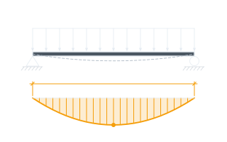
The load spread evenly along the span — self-weight, floor load on this member's share, a wall on it.
A floor load per square metre becomes a joist's line load when multiplied by the width of floor the joist carries: 1.5 kN/m² (31 psf) on joists at 400 mm (16 in) centres is 0.6 kN/m (41 lbf/ft).
A load concentrated at one place along the span — a post, a retained chimney breast, a tank's leg.
A load that sits across a short length, such as a chimney breast bearing across its own width, is close enough to a point load for screening when that length is small against the span.
Where along the span the point load sits, measured from one support.
At mid-span it bends the beam most; near a support it goes almost straight into the support and bends it little.
Maximum bending moment
10.2 kip·ft
A demand, not a capacity. The section that carries it is checked separately for bending, for shear at the larger reaction, and for deflection, which on a beam holding up masonry or plaster usually decides the size before strength does. The equivalent uniform load matches the point load on bending and over-states its deflection, so it is a screening figure for a table written in uniform loads, never a design.
- Where the moment peaks, from the left support
- 6.5 ft
- Left reaction
- 2.01 kips
- Right reaction
- 2.01 kips
- Moment from the point load alone
- 7.31 kip·ft
- Uniform load that bends the beam as much as the point load
- 345.86 lbf/ft
- End shear the point load puts into the nearer support
- 1.12 kips
- End shear the equivalent uniform load gives
- 2.25 kips
- The two maxima added (safe-side shortcut)
- 10.2 kip·ft
They open the calculator with your figures already in it
Beam and Joist Point Load Moment Calculator (Equivalent UDL): 10.2 kip·ft — shown in imperial, US market. The link sets both, so the result they see is the one on your screen.
Show calculation logicHide calculation logic
How this was calculated
Formula source(s)
- Simply supported beam (AISC Steel Construction Manual, Table 3-23, beam diagrams 1 and 7): a uniform load w gives R = wL/2 at each end and M = wL²/8 at mid-span; a point load P at a from one end and b from the other gives R1 = Pb/L, R2 = Pa/L and M = Pab/L under the load; combined, the moment peaks where the shear crosses zero
- The uniform load giving the same peak moment as the point load alone: w = 8Pab ÷ L³, which is 2P ÷ L for a load at mid-span
Inputs used
- Span Between Supports
- 13 ft
- Uniform Load Along the Beam
- 137.04 lbf/ft
- Point Load
- 2.25 kip
- Distance of the Point Load from the Left Support
- 6.5 ft
Intermediate steps
- Where the moment peaks, from the left support
- 6.5 ft
- Left reaction
- 2.01 kips
- Right reaction
- 2.01 kips
- Moment from the point load alone
- 7.31 kip·ft
- Uniform load that bends the beam as much as the point load
- 345.86 lbf/ft
- End shear the point load puts into the nearer support
- 1.12 kips
- End shear the equivalent uniform load gives
- 2.25 kips
- The two maxima added (safe-side shortcut)
- 10.2 kip·ft
Confidence note: A demand, not a capacity. The section that carries it is checked separately for bending, for shear at the larger reaction, and for deflection, which on a beam holding up masonry or plaster usually decides the size before strength does. The equivalent uniform load matches the point load on bending and over-states its deflection, so it is a screening figure for a table written in uniform loads, never a design.
What this calculation does not cover
- One span, simply supported, with one point load. A continuous beam, a cantilever or several point loads need their own analysis.
- The loads are taken as given, with no factors. Characteristic loads give a working moment; a limit-state design applies the partial factors of the code in force before the section is checked.
- A load spread over a length that is a real share of the span — a wide chimney breast on a short beam — is a patch load, whose peak moment is lower than the point load's; treating it as a point is on the safe side.
Add the equipment this sizes
This result is a specification — 10.2 kip·ft — not a quantity. Put the thing it sizes into your project: how many, what you call it, and your supplier’s price.
Computed in your browser — nothing you enter is uploaded. Presented in US customary units and US trade terminology. Where a formula follows a published standard, that standard and its edition are cited beside it on this page; where none governs, the page says so. Local amendments override model codes — verify against the code in force where you build.
Sources checked 2026-09-22 · v1.0.0
Regulatory standards & verification citations2
- Simply supported beam (AISC Steel Construction Manual, Table 3-23, beam diagrams 1 and 7): a uniform load w gives R = wL/2 at each end and M = wL²/8 at mid-span; a point load P at a from one end and b from the other gives R1 = Pb/L, R2 = Pa/L and M = Pab/L under the load; combined, the moment peaks where the shear crosses zero
- The uniform load giving the same peak moment as the point load alone: w = 8Pab ÷ L³, which is 2P ÷ L for a load at mid-span
Cite this page
Your workspace
Most jobs need more than one number. Add the calculators you need next and they open right here, underneath this one — your figures stay on screen and nothing is lost to a page change.