
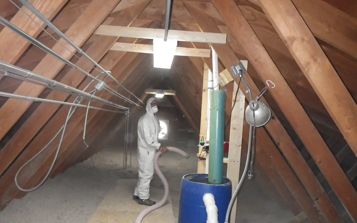
Twelve Metres to the Haunch, Six Doors on a Cycle
One hundred and twenty metres by seventy-eight, twelve to the haunch and fourteen to the ridge: nine and a third thousand square metres of floor under something like a hundred and seventeen thousand cubic metres of air. Racking to eleven metres in the bulk aisles, a pick face down one side, six dock levellers and two full-height doors at the west end, forty people on foot and a dozen trucks, and an office block bolted to the gable with its own comfort expectations. The tender went out asking for radiant tube. The incumbent contractor has come back proposing cabinet heaters with destratification fans and a saving on the capital, and the operator wants to know which of them is telling the truth.
The thing that separates this from every other heating job is not the size. It is that nearly all the volume sits above anybody's head, the envelope has a hole in it that opens on a schedule, and the calculated heat loss depends on which system you pick — so the usual sequence of load first, equipment second, does not close. Warm air builds a temperature gradient that increases the loss through the roof it is sized against. Radiant charges the floor slab and increases the loss through the ground. Both loops have to be walked round once before a number means anything, which is why the setpoint, the envelope and the doors get settled here before anything is hung from the steelwork.
The Setpoint Is a Height Before It Is a Number
Sixteen degrees is the figure that lands in the specification, and in Great Britain it has a source: the Approved Code of Practice to the Workplace (Health, Safety and Welfare) Regulations 1992, published as HSE L24, says the temperature in workrooms should normally be at least 16 °C, or 13 °C where much of the work involves severe physical effort. In the United States there is no equivalent numeric rule — OSHA has no workplace temperature standard and reaches these cases through the General Duty Clause at Section 5(a)(1) of the OSH Act — so the contract figure is whatever the operator and the designer agree it is. Either way the number on its own commissions nothing. Sixteen degrees where? At what height, how far from the dock, and how long after a trailer has pulled off the leveller?
It also matters which temperature is meant. Comfort responds to air temperature and to the temperature of the surfaces around a body in roughly equal measure at the low air speeds you get away from a fan jet, which is why CIBSE Guide A works in dry resultant temperature — the mean of air temperature and mean radiant temperature — and ASHRAE in operative temperature for the same reason. That average is the whole commercial case for radiant heating: lift the mean radiant temperature by two kelvin and the air can sit two kelvin lower for the same sensation. It is also the reason a radiant scheme measured with an ordinary air thermostat reads as a failure while the people underneath it are perfectly comfortable.
There is a limit to how far that trade can be pushed, and it is a comfort limit rather than an equipment one. Radiant asymmetry — a hot surface on one side of a body and a cold one on the other — is tabulated in ANSI/ASHRAE Standard 55 and ISO 7730, and the tightest of the four cases is a warm ceiling, at a few kelvin. A picker standing under a high-intensity emitter with a cold steel wall behind them can be at the right operative temperature and still be uncomfortable, which is why overhead intensity is capped by mounting height rather than by capacity.
So write the requirement the way it will be proved: an operative temperature, at a stated height above the finished floor, in named zones, at a named time in the shift pattern, with a tolerance and a recovery time after a dock cycle. Anything looser and the commissioning visit becomes an argument about where to hold the instrument.
Panel Datasheets Into Something You Can Multiply
Cladding gets quoted two different ways and the two do not share a scale. A European composite panel arrives with a U-value in W/m²K; a North American assembly arrives with an R-value in hr·ft²·°F/BTU. They are reciprocals within their own unit system and nowhere else: one square metre kelvin per watt is 5.678 hr·ft²·°F/BTU, so a roof at R-6 on the metric scale is about R-34 on the imperial one, and a schedule that mixes the two is wrong by a factor of five and a half. Before any reciprocal is taken, establish which scale the datasheet is on, and whether the figure includes the internal and external surface films that BS EN ISO 6946 counts as part of the assembly.
The panel is also not the assembly. Built-up systems carry a liner sheet, spacer rails and an outer sheet, and the rails bridge the insulation from inside to out; the effective U of the constructed roof is worse than the certificate for the insulation core, sometimes markedly so. A composite panel avoids most of that but keeps a joint every metre or so and a fixing through it. Whatever the system, take the figure from the assembly calculation rather than from the thickest layer in it.
Then look up. Rooflights are typically ten to fifteen per cent of a shed roof and they are the single biggest item on the heat loss schedule in most warehouses — twin or triple-skin GRP sits an order of magnitude above the panel around it. In the example building, the rooflights cover twelve per cent of the roof area and account for more than forty per cent of the above-ground fabric loss. That relationship, not the insulation thickness, is what decides whether the fabric is worth arguing about at all.
Heat loss multiplies through transmittance, not resistance, so every surface has to be turned over before it can go into a schedule — take the reciprocal once per assembly, after the layers have been added, and check the datasheet is on the same R scale you think it is.
The assembly's total thermal resistance.
U-value
0.05263 BTU/hr·ft²·°F
U = 1 ÷ R. The two are exact reciprocals of one another. R-values add across layers; U-values do not. Sum R first, then take the reciprocal once.
They open the calculator with your figures already in it
R-Value to U-Value Calculator: 0.0526 BTU/hr·ft²·°F — shown in imperial, US market. The link sets both, so the result they see is the one on your screen.
Add the equipment this sizes
This result is a specification — 0.05263 BTU/hr·ft²·°F — not a quantity. Put the thing it sizes into your project: how many, what you call it, and your supplier’s price.
What this calculation does not cover
- The conversion trusts the number you type and cannot tell a whole-assembly R from a product label. Insulation, sheathing, cladding, linings, cavities and the interior and exterior surface films all have to be totalled before the reciprocal is taken; a batt's rated R entered on its own returns the U-value of a wall that does not exist.
- Thermal bridging is not in it. Studs, plates, headers, rim joists, cladding fasteners and metal furring carry heat around the insulation, so a framed assembly performs worse than the reciprocal of its clear-field R. That figure comes from a parallel-path or isothermal-planes calculation, not from this one.
- A U-value describes steady-state, one-dimensional conduction and nothing else. Air leakage, wind-washing through loose-fill, convection in unsealed cavities, moisture in the material, thermal mass and solar gain all sit outside it, so a heat loss worked out as U x A x deltaT is the conduction share of the load rather than the whole load.
- R-value is quoted at a rating temperature and does not hold across all service conditions. Foil-faced polyiso in particular delivers less R per inch as the assembly gets cold, and foam boards drift as their blowing agent ages, so the R that applies on a design winter night may not be the one printed on the board.
- This is arithmetic, not a compliance check. Energy codes set maximum U-factors against specifically defined assemblies, and windows and doors are rated as whole units including frame and edge-of-glass, so inverting a glazing R will not answer either question. Everything on this page is imperial: a metric U in W/m2K is roughly 5.68 times the imperial figure shown here.
R and U describe the same physical property from opposite ends: resistance to heat flow, and the rate of heat flow itself. Insulation is marketed in R because bigger sounds better, while heat-loss calculations run on U because it multiplies straight through the Q equals U-A-delta-T relationship. The conversion is a pure reciprocal, and the mistake that ruins calculations is doing it too early. Resistances add in series — batt plus sheathing plus cladding plus air films — so the correct order is to total every layer's R and invert once at the end. Summing the individual U-values of each layer produces a number that is not merely imprecise but wrong, typically by a large margin.
Surface by Surface, With the Roof in a Different Room
The transmission arithmetic is the same as anywhere: transmittance times area times the temperature difference, once per surface, summed. What changes in a shed is the bookkeeping. The ground floor slab does not see outdoor design temperature and cannot be entered as though it did — BS EN ISO 13370 handles it through the perimeter-to-area ratio and a ground temperature, and in a building this wide that ratio is so low that even an uninsulated slab is a modest loss per square metre. The design outdoor condition comes from the climatic design data in the ASHRAE Handbook — Fundamentals or the equivalent national table, at the percentile the design method calls for, and BS EN 12831-1 is the corresponding European procedure for the whole calculation.
Run against a 16 °C internal and a −4 °C external design condition, the example shed comes out around 99 kW of above-ground fabric loss, plus roughly ten more through the slab on its much smaller temperature difference. That is a hundred and ten kilowatts for a building of nine and a third thousand square metres — a number most people find surprisingly small, and it is the reason so many warehouse schemes that were sized on fabric alone leave the dock end cold.
The correction that gets missed is on the temperature difference rather than on the areas. The roof and the rooflights are not exposed to the setpoint; they are exposed to whatever the air at high level is doing. Under a warm air system discharging above head height, the ceiling can sit well above the floor, and every kelvin of that gradient is applied across three and a half thousand watts per kelvin of roof and rooflight. Eight kelvin of stratification adds twenty-eight kilowatts to a hundred and ten kilowatt building — a quarter again, spent entirely on heating the underside of the roof.
Which means the loss is a property of the scheme. Compute it once at the setpoint to get the floor of the range, then recompute the roof surfaces at the high-level temperature the chosen system will actually produce, and expect radiant and warm air to give different answers for the same building. That iteration takes ten minutes and it is the difference between a plant schedule and a guess.
| Surface | Area | Assumed U-value | Loss per kelvin |
|---|---|---|---|
| Roof panel | 8,220 m² | 0.18 W/m²K | 1,480 W/K |
| Rooflights, three runs | 1,140 m² | 1.80 W/m²K | 2,052 W/K |
| Wall panel | 4,610 m² | 0.26 W/m²K | 1,199 W/K |
| Dock, vehicle and personnel doors | 140 m² | 1.50 W/m²K | 210 W/K |
| Above-ground subtotal | — | — | 4,941 W/K |
| Ground floor slab, on ground temperature | 9,360 m² | 0.14 W/m²K | 1,310 W/K |
It takes one surface at a time against an assembly R-value on the imperial scale, so the W/m²K in the schedule has to be turned over and rescaled by 5.678 before it is typed in — a rooflight at 1.80 W/m²K goes in as R-3.2, a roof panel at 0.18 as R-31.5. It also caps at 500 m², so a shed roof enters as a representative bay and scales by area. What no tool will do for you is the part that decides the answer: run each surface at the temperature difference that surface really sees, rather than the one on the front of the specification.
The area of the specific wall, window, roof, or floor surface being analyzed.
The insulating R-value of this specific surface assembly.
Your target indoor temperature.
Your region's extreme winter (or summer) design temperature, not the average.
Heat transmission load
944 BTU/hr
This computes conductive transmission loss through one surface using standard physics — a complete Manual J (or Manual N/CIBSE-equivalent) whole-building load calculation also accounts for air infiltration, internal gains, solar gain, and every surface combined.
- U-value
- 0.08 BTU/hr·ft²·°F
- Equivalent in watts
- 276.75 W
They open the calculator with your figures already in it
HVAC Thermal Load (U-Value) Calculator: 944 BTU/hr — shown in imperial, US market. The link sets both, so the result they see is the one on your screen.
Add the equipment this sizes
This result is a specification — 944 BTU/hr — not a quantity. Put the thing it sizes into your project: how many, what you call it, and your supplier’s price.
What this calculation does not cover
- Conduction through one surface, nothing else. Air leakage and ventilation, solar gain through glass, internal gains from people, lighting and appliances, latent (humidity) load, and duct or distribution losses are all outside the formula. Run it on every surface and add the results and you still have a transmission subtotal, not a heating or cooling load.
- This is not a Manual J, Manual N or CIBSE-equivalent load calculation and it is not a basis for selecting or sizing equipment. Where a jurisdiction, utility programme or inspector requires a load calculation, it will require a recognised whole-building method, not a per-surface transmission figure.
- The R-value is taken at face value. Thermal bridging through framing and fasteners, gaps and compressed insulation, wind washing at the edges, and the R-value loss some foams show at cold temperatures all put the real assembly below its nominal rating, and none of them are modelled here. Interior and exterior air films are not added either.
- Steady state, and a rate rather than a quantity. It answers what the surface loses at the instant both design temperatures hold; thermal mass, night setback and the daily temperature swing are absent, so the figure cannot be multiplied by hours to get fuel use, runtime or a bill.
- Surfaces that do not face outdoor air are out of scope. A slab, a basement wall or a floor over a crawl space exchanges heat against ground and buffer-space temperatures on a different basis, and the outdoor field clamps to −40 °C to 45 °C (−40 °F to 113 °F), a range that reaches neither a summer attic nor the coldest published design conditions in the far north.
The Loss That Walks In Through the Dock
Air changes per hour is the wrong unit for this building and it flatters it badly. Leakage happens at joints, laps, service penetrations and door seals, all of which are envelope quantities, so a tall shed divides the same defects by a much larger volume and reports a lower rate than a squat one with identical workmanship. That is why non-domestic air permeability is measured and specified per square metre of envelope at fifty pascals — the ATTMA Technical Standard L2 measurement behind an Approved Document L submission — rather than in air changes. Convert to air changes only at the end, for the heat loss line, and only against the volume you actually intend to heat.
Even then the number is large. A hundred and seventeen thousand cubic metres at a quarter of an air change an hour, warmed through twenty kelvin, is about a hundred and ninety kilowatts using the standard volumetric heat constant of roughly 0.33 W·h per cubic metre kelvin. That is nearly twice the entire fabric loss, at an infiltration rate a well-built modern shed would be pleased with. In a warehouse the air term is the design, and the fabric is the part that is easy to compute.
Then somebody opens a door. Stack pressure at an opening is outdoor air density times gravity times the height below the neutral plane times the inside-to-outside temperature difference divided by the absolute indoor temperature. Put a twelve metre shed with its neutral plane near mid-height and twenty kelvin across the wall into that, and floor level sees something close to five pascals — enough to drive roughly two metres per second inward across the lower part of the opening. A three by three dock door standing open can therefore pass tens of thousands of cubic metres an hour, and tempering that air runs to a couple of hundred kilowatts from one doorway. Discharge coefficients and the true neutral plane position make that an order-of-magnitude figure rather than a precise one, and the ventilation and infiltration chapter of the ASHRAE Handbook — Fundamentals is where the proper method lives. The order of magnitude is the point: no heating system on the market outruns a door management problem.
So the doors belong in the heating tender. Dock shelters or inflatable seals so a backed-in trailer closes the hole rather than framing it; fast-acting doors specified on the cycle time the traffic can really achieve, not the one on the brochure; air curtains tested to ANSI/AMCA Standard 220, which recent editions of ASHRAE 90.1 and the IECC have begun to accept as an alternative to a vestibule in some circumstances, so check the edition your authority has adopted; local heater interlocks that stop pouring heat at an open shutter; and, where the traffic genuinely never stops, tempered make-up air holding the building slightly positive so the leakage direction reverses.
The pressure at the door from this section's own figures: the opening's height below the neutral plane and the temperatures inside and out — the 12 m (39 ft) shed with its plane at mid-height and 20 K (36 °F) across the wall gives a little over five pascals at floor level — and the air speed it drives through an open door at a discharge coefficient of 0.65.
How far the opening is below (or above) the level where inside and outside pressures are equal.
Sets the direction the air moves; the size of the pressure depends only on the height.
The air temperature inside the building.
The outdoor air temperature.
How much of the ideal flow a real opening passes — about 0.65 for a large opening.
Stack pressure across the opening
5.21 Pa
Outside air is pushed in through this opening: the building is warmer than outside and the opening is below the neutral plane, or cooler and above it. The pressure grows in a straight line with the height from the neutral plane and with the temperature difference.
- The same pressure in inches of water gauge (in. w.g.)
- 0.02 in. w.g.
- Outdoor air density
- 0.08 pcf
- Air speed through the opening at this discharge coefficient
- 362.08 ft/min
They open the calculator with your figures already in it
Stack Effect Pressure Calculator: 5.21 Pa — shown in imperial, US market. The link sets both, so the result they see is the one on your screen.
Add the equipment this sizes
This result is a specification — 5.21 Pa — not a quantity. Put the thing it sizes into your project: how many, what you call it, and your supplier’s price.
What this calculation does not cover
- The neutral plane's position is an estimate: mid-height for evenly spread openings, lower when the large openings are low. Wind adds its own pressures on top, and on an exposed door it can dominate.
- The air speed is an order-of-magnitude figure. Discharge coefficients vary with the opening's shape, and flow through a large door is two-way — out at the top while it comes in at the bottom.
- Mechanical ventilation that holds the building above or below outside pressure moves the neutral plane and can reverse the flow at a given opening.
Radiant Tube: Warming the Slab, the Racking and the People
A low-intensity tube heater fires down a steel tube with a reflector above it, and what leaves the assembly is largely radiation aimed at the floor. The floor takes it, and a two-hundred-millimetre power-floated slab is a very large thermal store at a very low temperature. That is why radiant schemes recover so convincingly after a dock cycle: the heat that was in the building is still in the building, because it was never in the air that just left through the opening. It is also why the air above stays closer to the floor temperature, which trims both the roof loss and the stack pressure that drives infiltration in the first place.
The catch is geometric. An emitter heats what it can see, and eleven metres of racking in a narrow aisle sees mostly the tops of pallets. Radiant is at its strongest over defined occupied ground — pick faces, packing benches, goods-in, the marshalling area, the dock apron where somebody stands in a draught all shift — and at its weakest as a way of holding a uniform temperature through a bulk store nobody occupies. Spot-heating a cold work position is the single best value in the building; blanket-heating a full-height aisle with overhead radiant is the most expensive way to warm cardboard.
The constraints are hard ones. Minimum mounting height and clearance to combustibles are listing conditions from the appliance standards — ANSI Z83.20/CSA 2.34 for low-intensity gas-fired infrared, ANSI Z83.19/CSA 2.35 for high-intensity, BS EN 416 and BS EN 419 for the European equivalents — and they are not negotiable to suit a steel layout. Sprinklers rule the same zone: NFPA 13 requires clearance below deflectors and keeps obstruction rules over the storage, so tube runs and their hangers have to be coordinated with the sprinkler contractor before they are drawn, not after.
Unflued luminous heaters deserve a separate decision. They put their combustion products into the space, which BS EN 13410 answers with a ventilation requirement for the premises, and that ventilation is a heat loss you have just bought. They also put in the water: burning methane yields two molecules of water for every one of gas, about 1.6 kg of vapour per cubic metre burned, into a building that may be full of cardboard cartons and steel racking. Flued tube heaters avoid both problems and cost more to install. Control either type from a black-bulb or globe sensor — an ordinary air thermostat in a radiant space measures the one temperature the system is not trying to move.
Warm Air: Throw, Recirculation, and the Layer It Builds
A warm air scheme is a set of fans throwing jets, and the design question is where the jet stops. A cabinet heater with a nominal throw of eighteen metres set at the end of a twenty-five metre bay leaves a cold corner however many kilowatts are on its nameplate, and the correction is nozzle selection, discharge angle and unit position rather than more capacity. Indirect-fired units under ANSI Z83.8/CSA 2.6 or BS EN 1020 recirculate room air across a heat exchanger and vent their products outside; non-recirculating direct-fired units under ANSI Z83.4/CSA 3.7 burn into the airstream, put very nearly all the fuel energy into the space, and are the natural way to deliver tempered make-up air and hold the dock end positive against infiltration — with the ventilation rate that comes with combustion products in the supply.
What warm air cannot avoid is building the gradient it then has to pay for. Heat delivered as warm air rises, the ceiling zone warms first, and the calculation from the previous section runs in reverse: the more effectively the units heat, the more the roof loses. Gradients of several kelvin over the height are routinely measured in high-level discharge installations, and eight to ten kelvin is not unusual where nothing brings it back down. That is not an argument against warm air. It is an argument for measuring the gradient and either designing it out with discharge geometry or recovering it with fans, and for pricing that recovery in the same tender.
Where warm air wins outright is the door-poor, fabric-dominated shed with no fixed occupied zone; the building that needs mechanical ventilation anyway; the retrofit that already has the gas main, the flues and the electrical supply in the right places; and any scheme where the same plant has to serve ancillary spaces through ductwork, which no radiant system can do.
Mixing Them, and Reading Two Catalogues That Disagree on Units
Most real warehouses end up mixed, and the split follows the occupancy rather than the architecture: radiant over the dock apron, the pick face and the packing benches where people stand still, warm air through the bulk store and anywhere make-up air or ventilation is required regardless. Zone the two separately with their own sensors and their own schedules — the dock zone has a different loss, a different duty cycle and a different recovery requirement from the back of the building, and running them off one controller wastes both.
Then comes the comparison, and it is where honest tenders go wrong through units alone. European heaters are rated in kilowatts, sometimes on net calorific value and sometimes on gross — a factor of about 1.11 for natural gas, which is enough on its own to reorder a tender list. North American unit heaters publish an input in BTU per hour and an output in BTU per hour, differing by the thermal efficiency. Put an input from one column against an output from the other and you have flattered one supplier by a fifth without either of them doing anything wrong.
Radiant carries a third figure again. A tube heater's gas rate is an input; the fraction that leaves as radiation rather than as flue gas and convection is a separate published quantity, and it is the one that matters for a scheme sized against occupied ground rather than against room air. Compare radiant schemes on radiant output over the target area, compare warm air schemes on output at the burner, and convert everything to one unit on one side of the burner before anybody is ranked.
| As quoted | What it measures | Before comparison |
|---|---|---|
| kW, net (Hi) | Fuel energy in, excluding the latent heat of the flue water vapour | Convert to the same calorific basis as the other tender — roughly a factor of 1.11 for natural gas |
| kW, gross (Hs) | Fuel energy in, including that latent heat | State the basis on the schedule; a condensing appliance is the only one that can recover it |
| BTU/h input | Gas rate at the burner | Multiply by the published thermal efficiency to get useful output |
| BTU/h output | Heat delivered to the space | Convert to kW, or convert the other column to BTU/h — never mix the two |
| Radiant output or radiant factor | The share leaving as radiation rather than convection or flue loss | Apply to the emitter's coverage over the occupied area, not to the building volume |
Two tenders quoted in two unit systems cannot be ranked until they are in one, and the conversion is the easy half — the half that costs money is remembering whether the figure you just converted was an input or an output.
The rated heating or cooling output in kilowatts.
Equivalent output
11,940 BTU/hr
Converted using an exact defined factor of 3412.141633127968 BTU/hr per kW. Manufacturers round nameplate figures heavily, so a 3.5 kW unit is usually sold as 12,000 BTU/h rather than the exact 11,942.
- Conversion factor applied
- 3,412.14 BTU/hr per kW
They open the calculator with your figures already in it
kW to BTU/hr Calculator: 11,942 BTU/hr — shown in imperial, US market. The link sets both, so the result they see is the one on your screen.
Add the equipment this sizes
This result is a specification — 11,940 BTU/hr — not a quantity. Put the thing it sizes into your project: how many, what you call it, and your supplier’s price.
What this calculation does not cover
- This converts a rating you already have. It is not a heat-loss or heat-gain calculation, so it cannot tell you whether that kilowatt figure is the right capacity for the space — sizing still needs a room-by-room load calculation against your own design conditions.
- The conversion does not know what your kilowatt figure represents. Thermal output, electrical input, and gas input on a net or gross calorific basis all appear as kW on datasheets and are all treated identically here. Compare output against output, or you flatter one machine over another before any arithmetic happens.
- Rating conditions do not travel with the number. A heat pump's kW figure is quoted at particular indoor and outdoor temperatures and falls away as it gets colder outside, and the same machine usually carries different heating and cooling ratings. The BTU/hr you get back describes only the single rating point you typed in.
- The answer is arithmetic, not a catalogue size. Equipment sells in nominal steps with a tolerance band around each, and nothing here snaps the figure to a size a manufacturer actually builds or tells you what the unit you order will test at.
- Nothing here sizes an electrical supply. BTU/hr is heat moved or produced, not power drawn — take circuit, breaker and cable sizing from the nameplate's running current and minimum circuit ampacity, never from a converted capacity.
European and Australian equipment is rated in kilowatts while American catalogues, permits and rebate schedules still work in BTU per hour, so anyone specifying a US-market unit from a metric datasheet has to move between the two. The arithmetic is exact — a kilowatt is 3,412.14 BTU/h by definition — but the practical trap is rounding: the industry sells in nominal sizes, so a 3.5 kW output is marketed as a 12,000 BTU/h or one-ton unit even though the true conversion is 11,942 BTU/h. Specify against the nominal size the catalogue uses, and keep the exact figure for load calculations rather than for ordering. Note too that a heat pump's thermal output and its electrical draw are different numbers: converting the input power instead of the rated capacity will undersize the equipment by whatever its coefficient of performance happens to be.
Destratification, and the Fans the Sprinkler Layout Will Allow
Measure before buying. A string of loggers up a column at one, three, six, nine and twelve metres, left through a fortnight of heating weather, settles the destratification argument in a way no brochure can: it tells you whether there is anything up there worth bringing down. A radiant scheme frequently shows a kelvin or two over the full height and has nothing to recover. A warm air scheme with high-level discharge and no mixing can show eight or ten, and that is a genuine prize.
Size the prize before the fans. In the example shed, roof and rooflights together lose about 3,530 watts per kelvin, so eight kelvin of stratification is roughly twenty-eight kilowatts of plant heating the roof void — a real number to set against fan capital and fan running cost, rather than a percentage saving from a supplier's case study. Fans also cost heat in another way if they are run in summer or run too fast in winter: air movement across a standing worker is a cooling sensation, and a destratification fan is meant to overturn the volume slowly, not to ventilate the picker.
Then find out what may be hung. NFPA 13 sets specific limits on high-volume low-speed fans in sprinklered buildings — a maximum diameter, a position centred between four adjacent sprinklers, a minimum vertical clearance below the deflectors, and an interlock that shuts the fan down on a waterflow signal — and FM Global's installation guidelines for automatic sprinklers restate equivalent restrictions for FM-insured property. Take those to the sprinkler contractor before fan positions reach a drawing. A fan relocated late is a fan that ends up over a rack aisle, moving air through steel and pallets where nobody is standing.
One warning about sizing tools. The published blade-diameter chart used for rooms is not an HVLS selection method; large industrial fans are selected on tested airflow to the AMCA methods and on the manufacturer's coverage diameter at a stated mounting height and speed. What the chart is right for is the rooms inside the shed — the transport office, the mess room, the gatehouse — which are ordinary rooms with ordinary ceilings.
For the offices, mess room and gatehouse inside the shed this is the chart that applies, and it caps out well below a warehouse floor plate on purpose — the main volume is an HVLS selection made on tested airflow and coverage diameter, not on blade span.
The floor area of the room where the fan will be installed.
Recommended fan diameter
44 in (44 in)
This is a general sizing chart — ceiling height, mounting type (standard, low-profile, or downrod), and room shape can shift the ideal size within the suggested range.
- Room area
- 220 sq ft
They open the calculator with your figures already in it
Ceiling Fan Size Calculator: 44 in (44 in) — shown in imperial, US market. The link sets both, so the result they see is the one on your screen.
Add the equipment this sizes
This result is a specification — 44 in (44 in) — not a quantity. Put the thing it sizes into your project: how many, what you call it, and your supplier’s price.
What this calculation does not cover
- Floor area is the only input. Ceiling height, room shape and where the fan hangs are not modelled, so a long or L-shaped room returns the same size as a square one of equal area — and a large or irregular space that would be better served by two smaller fans still gets a single recommendation.
- This is a comfort-airflow chart, not an electrical or structural check. It says nothing about the branch circuit, the switch or speed control, or whether the ceiling box the fan will hang from is rated to carry a fan's weight and movement — a standard lighting outlet box is not.
- The fan itself is not modelled. Blade pitch, blade count, motor type and rated airflow vary widely between fans of the same diameter, so two fans that both match this recommendation can move very different amounts of air.
- Blade-tip clearance is not checked. Because the answer comes from area alone, a narrow room can be handed a diameter that leaves less clearance to the walls than the fan's own instructions require — measure the shortest wall-to-wall dimension before ordering.
- Mounting height, downrod length and location rating are outside this calculation. A sloped ceiling, a low ceiling, or a damp or wet location such as a covered porch or bathroom each impose their own requirements on the fan you can install, whatever size the area suggests.
The Office Block Bolted to the Gable
The offices are a different building sharing a wall. They run at twenty or twenty-one degrees rather than sixteen, on a different schedule, with people, screens, lighting and glazing, and they are usually cooling-led even in a heating climate. The mezzanine ones are worse: they sit inside the warm layer the shed's own heating creates, take solar gain through the rooflights above them, and can need cooling in January while the dock end is calling for heat.
The methods differ too, and mixing them is the usual mistake. The shed goes through a design heat loss procedure such as BS EN 12831-1, or the equivalent method in the ASHRAE Handbook — Fundamentals, against its own internal design condition. The office block is a light commercial load calculation, which is ACCA Manual N territory; Manual J is a residential procedure and stops at the front door of a house. A screening number is for the budget conversation and the sanity check, never for a submission.
Screen the office block on its own envelope area, an area-weighted average U-value and its own air change rate. It returns a steady-state heat loss, not the cooling figure the offices will in the end be sized on, and its volume ceiling of twenty thousand cubic metres is about a sixth of this shed — which is the correct behaviour, because the warehouse is neither a residential load nor a screening job.
Walls, roof, floor and glazing combined.
Area-weighted average through the whole envelope.
Floor area times ceiling height.
Infiltration and ventilation rate.
Internal design temperature minus external design temperature.
Design heat loss
5,710 W
Steady-state whole-house loss. Sound as a screening figure and as a check on a quote; not a substitute for a room-by-room calculation, which is what sizes emitters.
- Fabric loss
- 4,321.11 W
- Ventilation loss
- 1,386.05 W
- Kilowatts
- 5.71 kW
- BTU/h
- 19,473.63 BTU/h
- Ventilation as a share of the total
- 24.29 %
They open the calculator with your figures already in it
Heating & Cooling Load Screening Calculator: 5,707 W — shown in imperial, US market. The link sets both, so the result they see is the one on your screen.
Add the equipment this sizes
This result is a specification — 5,710 W — not a quantity. Put the thing it sizes into your project: how many, what you call it, and your supplier’s price.
What this calculation does not cover
- Whole-house, not room-by-room. It cannot size a radiator or a diffuser, only the plant.
- Steady-state: no solar gain, no internal gains from people and appliances, and no thermal mass. In a well-glazed house solar gain materially reduces the heating requirement and materially increases the cooling one.
- The air-change rate is an assumption unless it came from a blower-door test, and it is often the largest single term.
Proving It in Heating Weather
Commissioning a warehouse heating system in September proves nothing that matters. The proof is a cold morning with the doors working: black-bulb readings at the specified height in each zone, the gradient loggers still on the column, the gas rate checked at the meter against the schedule, the flue and combustion figures recorded, and somebody opening a dock door on purpose while a second person watches what the local heaters and the air curtain do about it.
The gas side has its own paperwork and its own competence requirements — NFPA 54/ANSI Z223.1 for venting, shut-offs and combustion air in North America, IGEM/UP/2 for pipework on industrial and commercial premises in the UK — and the ventilation provision for any unflued appliance has to be demonstrated rather than assumed. Where an energy standard applies, whether ASHRAE 90.1, the IECC's commercial provisions or Approved Document L Volume 2 with the Non-Domestic Building Services Compliance Guide, minimum efficiencies and control requirements for radiant and warm air plant are stated there, and the compliance evidence is easier to gather during commissioning than to reconstruct afterwards.
What the operator should be left holding is the argument, not just the certificates: the loss schedule surface by surface, the gradient the building actually runs at, the zone map, the sensor types and where they are, and the interlock logic. In five years somebody will propose adding a mezzanine, closing a door permanently or extending the racking to the roof, and every one of those changes a term in the calculation the system was sized from.
- Log air temperature up a column at several heights for a fortnight of heating weather, before and after any destratification is fitted.
- Take black-bulb readings at the contract height in each occupied zone, not air temperature at a convenient column.
- Check the gas rate at the meter against the scheduled input for each appliance, and record flue and combustion readings.
- Open a dock door with the building at setpoint and time the recovery in the nearest zone.
- Prove every interlock by operating it — door contacts, waterflow signal to the HVLS fans, and the local heater inhibit.
- Record the destratification fan speeds and directions that were commissioned, because the next person to touch them will have no other reference.
- Hand over the loss schedule and the zone map with the O&M, so the next alteration can be checked against the assumptions rather than against the invoice.
Before the tender goes out
The order matters more than the arithmetic here, because the equipment choice changes two of the inputs. Get the envelope and the air onto paper first, then let the two schemes compete against the same numbers.
- Rooflight area, separately from the roof — Usually a tenth of the roof and nearly half the above-ground loss; if it is not on its own line, the schedule is hiding its biggest item.
- Every assembly turned from R into U once — After the layers and surface films have been added, and on a stated unit scale — metric and imperial R differ by a factor of 5.678.
- Roof surfaces run twice — Once at the setpoint, once at the high-level temperature the chosen system will produce; the gap between those two answers is the destratification case.
- Volume, envelope area and the door schedule — Air permeability is measured per square metre of envelope; the air change rate is derived at the end, and the open-door hours are a separate line again.
- Heater outputs on one unit and one side of the burner — Net or gross kW, input or output BTU/h, radiant output over the target area — three different quantities that all look like a heater rating.
- The office block priced as its own building — Different setpoint, different schedule, cooling-led, and a commercial load method rather than the shed's design heat loss.
Opens the calculators above on one screen with the dimensions from this article already filled in. Quantities only — this site publishes no price list, because local prices vary too much to publish honestly.