
SettingsSettings for this calculationUS
From the manufacturer's blower table, at the airflow the system is designed to move.
The rated external static pressure on the data plate is the pressure at one fan speed; the blower table gives it at each airflow, and the design airflow is the one that counts.
From the component maker's data at the design airflow.
Every device in the air path spends part of the blower's pressure before any duct does: coils and filters most, then registers, grilles and dampers. A filter's drop rises as it loads, so a design uses a dirty-filter figure.
From the component maker's data at the design airflow.
Every device in the air path spends part of the blower's pressure before any duct does: coils and filters most, then registers, grilles and dampers. A filter's drop rises as it loads, so a design uses a dirty-filter figure.
From the component maker's data at the design airflow.
Every device in the air path spends part of the blower's pressure before any duct does: coils and filters most, then registers, grilles and dampers. A filter's drop rises as it loads, so a design uses a dirty-filter figure.
From the component maker's data at the design airflow.
Every device in the air path spends part of the blower's pressure before any duct does: coils and filters most, then registers, grilles and dampers. A filter's drop rises as it loads, so a design uses a dirty-filter figure.
From the component maker's data at the design airflow.
Every device in the air path spends part of the blower's pressure before any duct does: coils and filters most, then registers, grilles and dampers. A filter's drop rises as it loads, so a design uses a dirty-filter figure.
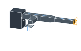
The measured run from the plenum to the farthest outlet plus the equivalent length of every fitting on it.
Fittings add far more than the straight duct: an elbow or a takeoff can be worth tens of feet of duct each, from the Manual D fitting tables.
The same for the longest return path, from the most remote grille back to the unit.
Supply and return together form the critical circuit; the shorter runs are balanced back with dampers.
Design friction rate
0.04 in. w.g./100 ft
The ducts may spend what the components leave of the blower's pressure, spread evenly over the longest supply and return runs.
- The components' pressure drops together
- 0.36 in. w.g.
- Available static pressure for the ducts
- 0.14 in. w.g.
- Total effective length, supply plus return
- 350 ft
They open the calculator with your figures already in it
Duct Design Friction Rate Calculator (ACCA Manual D): 0.04 in. w.g./100 ft — shown in imperial, US market. The link sets both, so the result they see is the one on your screen.
Show calculation logicHide calculation logic
How this was calculated
Formula source(s)
- ACCA Manual D, Residential Duct Systems — the friction rate worksheet: available static pressure = the blower's external static pressure at the design airflow − the component pressure drops; friction rate = available static pressure × 100 ÷ total effective length
- Total effective length = the longest supply run plus the longest return run, each with the equivalent length of its fittings
Inputs used
- Blower External Static Pressure at the Design Airflow
- 0.5 in. w.g.
- Cooling Coil Pressure Drop
- 0.2 in. w.g.
- Filter Pressure Drop
- 0.1 in. w.g.
- Supply Outlet Pressure Drop
- 0.03 in. w.g.
- Return Grille Pressure Drop
- 0.03 in. w.g.
- Other Components (dampers, humidifier; 0 if none)
- 0 in. w.g.
- Total Effective Length of the Longest Supply Run
- 250 ft
- Total Effective Length of the Longest Return Run
- 100 ft
Intermediate steps
- The components' pressure drops together
- 0.36 in. w.g.
- Available static pressure for the ducts
- 0.14 in. w.g.
- Total effective length, supply plus return
- 350 ft
Confidence note: The ducts may spend what the components leave of the blower's pressure, spread evenly over the longest supply and return runs.
What this calculation does not cover
- Read the blower's external static pressure at the design airflow from its table, not the rated figure on the data plate, and the component drops at the same airflow.
- The friction rate sizes the ducts for friction; velocity is a separate limit for noise, and a trunk sized correctly for friction can still be too fast. Size for friction, then check the velocity.
- Flexible duct has a higher friction than the sheet-metal values of a duct calculator or wheel, and loses more when it is compressed or sags.
Add the equipment this sizes
This result is a specification — 0.04 in. w.g./100 ft — not a quantity. Put the thing it sizes into your project: how many, what you call it, and your supplier’s price.
Computed in your browser — nothing you enter is uploaded. Presented in US customary units and US trade terminology. Where a formula follows a published standard, that standard and its edition are cited beside it on this page; where none governs, the page says so. Local amendments override model codes — verify against the code in force where you build.
Sources checked 2026-09-22 · v1.0.0
Regulatory standards & verification citations2
- ACCA Manual D, Residential Duct Systems — the friction rate worksheet: available static pressure = the blower's external static pressure at the design airflow − the component pressure drops; friction rate = available static pressure × 100 ÷ total effective length
- Total effective length = the longest supply run plus the longest return run, each with the equivalent length of its fittings
Which documents these citations point at
Standards referenced: ACCA Manual D (Air Conditioning Contractors of America, United States).
Cite this page
Your workspace
Most jobs need more than one number. Add the calculators you need next and they open right here, underneath this one — your figures stay on screen and nothing is lost to a page change.