
SettingsSettings for this calculationUS
The factored moment the connection must resist.
Use the design (factored) moment from your structural analysis for this connection.
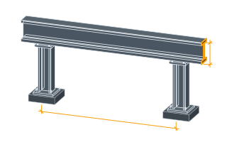
The distance between the extreme tension and compression bolt rows (or bolt row and compression flange).
This is a simplified couple-arm approximation, not a full elastic or plastic bolt-group analysis.
The rated shear or tension capacity of a single bolt for this connection.
Use the bolt's design capacity for the governing limit state (shear or tension) per AISC 360 or your applicable code, for the specific bolt grade and diameter.
Bolts needed
8 bolts
A simplified equivalent-force method — a full moment connection design also checks bolt group eccentricity, prying action, and plate bending per AISC 360 Chapter J and should be verified by a structural engineer.
- Equivalent force at bolt group
- 82.98 kips
They open the calculator with your figures already in it
Steel Moment Connection Bolt Count Calculator: 8 bolts — shown in imperial, US market. The link sets both, so the result they see is the one on your screen.
Show calculation logicHide calculation logic
How this was calculated
Formula source(s)
- Simplified moment-connection bolt force: equivalent force = applied moment ÷ effective lever arm between bolt rows; required bolts = ceil(equivalent force ÷ per-bolt rated shear/tension capacity)
Inputs used
- Applied Moment (kN·m)
- 150
- Effective Lever Arm Between Bolt Rows
- 1.33 ft
- Per-Bolt Rated Capacity
- 11.24 kip
Intermediate steps
- Equivalent force at bolt group
- 82.98 kips
Confidence note: A simplified equivalent-force method — a full moment connection design also checks bolt group eccentricity, prying action, and plate bending per AISC 360 Chapter J and should be verified by a structural engineer.
What this calculation does not cover
- The count assumes the lever arm entered survives the layout, and it has no idea whether the bolts fit. Spacing of about three diameters and the edge distances in AISC Table J3.4 have to be found within the end-plate width and either side of the beam flange, so a count of twelve on a 400 mm (16 in) arm can force the rows apart — changing the arm — or add a row inside the couple that does not carry the same force. Where the number will not fit the geometry, the connection changes, not the bolt count.
- A moment connection carries the beam's vertical reaction as well as its moment, and this divides the moment alone. Shear normally goes through a separate web plate and its own bolt group; where the same bolts take both, tension and shear interact and each bolt's available capacity drops below its tabulated single-action value, so a group sized here for the couple can be short once the reaction is added.
- Everything counted is on the beam side. The couple delivers its force into the column, whose flange bends, whose web yields, crumples or buckles opposite the compression flange, and whose panel zone shears — the checks that decide whether continuity plates, a doubler plate or a heavier column are needed. Those are what usually add the cost to a moment connection, and none of them changes the number of bolts returned here.
Estimated cost — your price
This site holds no price list for this material — local prices vary too much to publish honestly. Enter your supplier's price and the result is costed with it.
Computed in your browser — nothing you enter is uploaded. Presented in US customary units and US trade terminology. Where a formula follows a published standard, that standard and its edition are cited beside it on this page; where none governs, the page says so. Local amendments override model codes — verify against the code in force where you build.
Sources checked 2026-09-06 · in the site-wide review of 2026-09-06 · v1.0.1
Regulatory standards & verification citations1
- Simplified moment-connection bolt force: equivalent force = applied moment ÷ effective lever arm between bolt rows; required bolts = ceil(equivalent force ÷ per-bolt rated shear/tension capacity)
Cite this page
Your workspace
Most jobs need more than one number. Add the calculators you need next and they open right here, underneath this one — your figures stay on screen and nothing is lost to a page change.