
SettingsSettings for this calculationUS
The site's ground snow load, read from the map or table your code adopts.
Ground snow load drives both the drift height and the density of the snow forming it, so it appears twice in this calculation. Use the mapped or case-study value for the site, not a regional average — mountainous areas are case-study zones precisely because the map cannot represent them.
The balanced load already established for the lower roof, before any drift is added.
This is the pf that comes out of the flat-roof calculation — ground snow load reduced by the exposure, thermal and importance factors. It is needed here because it fixes the depth of balanced snow already lying on the roof, and the drift can only build in whatever height is left above it.
The step from the lower roof surface up to the upper roof surface at the wall.
Measure surface to surface, not parapet to parapet. This step sets the ceiling on the drift: once the drift reaches the upper roof level it stops growing taller and starts growing outward instead, which is the truncated case this page reports separately.
The length of upper roof the wind crosses before it reaches the step — the leeward source.
Snow is scoured off this length and dropped in the lee of the step, so the longer it is the bigger the drift. Measure in the direction of the governing wind; a roof that steps down on more than one side needs the check repeated for each.
The run of the lower roof away from the wall — the fetch for the windward case.
In the windward case the wind blows across the LOW roof and piles snow against the tall wall, so this length is what feeds the drift. It also limits how far a drift of either kind can physically extend before it runs off the edge.
Which side the wind is coming from relative to the step.
Both cases have to be checked at every step and the larger one governs, because wind does not commit to one direction for a winter. They differ in which roof supplies the snow and therefore in which length is the fetch, and the windward drift is taken at three quarters of the leeward height for the same fetch.
Peak drift surcharge at the wall
63.7 psf
The drift fits below the upper roof level, so its height is set by the fetch and the ground snow load. This is a surcharge to be added to the balanced load, not a replacement for it.
- Drift height at the wall
- 3.53 ft
- Horizontal extent of the drift
- 14.11 ft
- Balanced snow depth on the lower roof
- 1.21 ft
- Clear height above the balanced snow
- 6.79 ft
- Snow density used
- 18.07 pcf
- Drift height before truncation
- 3.53 ft
- Clear height over balanced depth
- 5.59 ratio
They open the calculator with your figures already in it
Roof Snow Drift Surcharge Calculator: 63.73 psf — shown in imperial, US market. The link sets both, so the result they see is the one on your screen.
Show calculation logicHide calculation logic
How this was calculated
Formula source(s)
- ASCE/SEI 7 Minimum Design Loads and Associated Criteria for Buildings and Other Structures, Chapter 7 drift provisions — leeward drift height hd = 0.43 x (lu)^(1/3) x (pg + 10)^(1/4) - 1.5, with the upwind fetch lu in feet, the ground snow load pg in psf and hd in feet; the windward case is taken as 0.75 of that value using the lower roof's own length as the fetch
- Snow density from the same chapter: gamma = 0.13 x pg + 14, capped at 30 pcf, which converts a snow load into the depth of snow that produces it
- Drift geometry from the same chapter: the drift is a triangle of width 4 x hd where it fits below the clear height hc; where hd would exceed hc the drift truncates at hc and widens to 4 x hd² / hc, not more than 8 x hc
- ASCE/SEI 7 also states that drift need not be considered where the ratio hc / hb is less than 0.2 — reported here rather than applied silently, because it is a decision the engineer makes
Inputs used
- Ground Snow Load pg
- 31.33 psf
- Balanced Roof Snow Load pf on the Lower Roof
- 21.93 psf
- Height Difference Between the Two Roofs
- 8 ft
- Upwind Fetch on the Upper Roof
- 98 ft
- Length of the Lower Roof
- 49 ft
- Drift Case
- Leeward — wind crosses the upper roof and drops snow behind the step
Intermediate steps
- Drift height at the wall
- 3.53 ft
- Horizontal extent of the drift
- 14.11 ft
- Balanced snow depth on the lower roof
- 1.21 ft
- Clear height above the balanced snow
- 6.79 ft
- Snow density used
- 18.07 pcf
- Drift height before truncation
- 3.53 ft
- Clear height over balanced depth
- 5.59 ratio
Confidence note: The drift fits below the upper roof level, so its height is set by the fetch and the ground snow load. This is a surcharge to be added to the balanced load, not a replacement for it.
What this calculation does not cover
- One step, one wind direction, one case at a time. Every step needs both cases checked and the larger taken.
- The surcharge reported is the PEAK at the wall; the drift tapers linearly to zero at its far edge.
- Sliding snow from a sloped upper roof, rain-on-snow surcharge and unbalanced loads on the upper roof are separate provisions.
- Drift equations differ between editions of ASCE 7 — confirm the form above against the edition your jurisdiction has adopted.
Add the equipment this sizes
This result is a specification — 63.7 psf — not a quantity. Put the thing it sizes into your project: how many, what you call it, and your supplier’s price.
Computed in your browser — nothing you enter is uploaded. Presented in US customary units and US trade terminology. Where a formula follows a published standard, that standard and its edition are cited beside it on this page; where none governs, the page says so. Local amendments override model codes — verify against the code in force where you build.
Sources checked 2026-08-30 · in the site-wide review of 2026-09-06 · v1.0.0
Regulatory standards & verification citations4
- ASCE/SEI 7 Minimum Design Loads and Associated Criteria for Buildings and Other Structures, Chapter 7 drift provisions — leeward drift height hd = 0.43 x (lu)^(1/3) x (pg + 10)^(1/4) - 1.5, with the upwind fetch lu in feet, the ground snow load pg in psf and hd in feet; the windward case is taken as 0.75 of that value using the lower roof's own length as the fetch
- Snow density from the same chapter: gamma = 0.13 x pg + 14, capped at 30 pcf, which converts a snow load into the depth of snow that produces it
- Drift geometry from the same chapter: the drift is a triangle of width 4 x hd where it fits below the clear height hc; where hd would exceed hc the drift truncates at hc and widens to 4 x hd² / hc, not more than 8 x hc
- ASCE/SEI 7 also states that drift need not be considered where the ratio hc / hb is less than 0.2 — reported here rather than applied silently, because it is a decision the engineer makes
Cite this page
Your workspace
Most jobs need more than one number. Add the calculators you need next and they open right here, underneath this one — your figures stay on screen and nothing is lost to a page change.
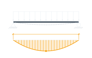
The drift stands 3.53 ft (1.07 m) against the wall and reaches 14.11 ft (4.30 m) out across the lower roof, tapering to nothing at its far edge. The surcharge shown is the peak value at the wall and is added on top of the balanced load, not instead of it.