
SettingsSettings for this calculationUS
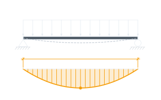
The uniformly distributed load on the tray, including cables and the tray's own weight, per unit length.
Sum the weight of all cables carried plus the tray's self-weight, expressed per meter of span, to get the uniformly distributed load used in the beam deflection formula.
The distance between adjacent tray supports.
Measure center-to-center between the two supports bracketing the span being checked.
The tray rail material's modulus of elasticity.
Steel tray rail is commonly around 200,000 MPa; aluminum tray rail is commonly around 70,000 MPa. Check the manufacturer's data for your specific tray.
The tray rail cross-section's moment of inertia, a measure of its bending stiffness.
Look up the moment of inertia for the specific tray rail section (side rail profile and depth) from the manufacturer's load/span tables.
Calculated center-span deflection
0.00553 in
The centre-span deflection this tray works out to is below the L/100 limit for the support span entered shown with it — The L/100 convention NEMA VE 1 load/deflection ratings are referenced against gives it. Being under one limit is not a design. Nothing else is checked here — not the other limit states, not the connections, not the member the load arrives from.
- L/100 allowable limit (NEMA VE 1)
- 1.2 in
They open the calculator with your figures already in it
Cable Tray Center-Span Deflection Calculator: 0.0055 in — shown in imperial, US market. The link sets both, so the result they see is the one on your screen.
Show calculation logicHide calculation logic
How this was calculated
Formula source(s)
- Uniformly-loaded simple beam deflection: Δ = 5wL⁴/(384EI), applied to a cable tray section between supports; standard cable tray deflection limit per NEMA VE 1 load/deflection test rating is commonly L/100 of the support span
Inputs used
- Total Cable + Tray Load (N/m)
- 50
- Support Span Length
- 10 ft
- Tray Rail Modulus of Elasticity E
- 29007547.55 psi
- Tray Rail Moment of Inertia I (×10⁶ mm⁴)
- 2
Intermediate steps
- L/100 allowable limit (NEMA VE 1)
- 1.2 in
Confidence note: The centre-span deflection this tray works out to is below the L/100 limit for the support span entered shown with it — The L/100 convention NEMA VE 1 load/deflection ratings are referenced against gives it. Being under one limit is not a design. Nothing else is checked here — not the other limit states, not the connections, not the member the load arrives from.
What this calculation does not cover
- Solves one simply supported span, which is the softest case and rarely the built one. Tray normally runs continuous over several supports, and where the splices sit decides which case applies: a splice landing near mid-span puts a hinge at the point of maximum moment and multiplies this figure, while splices kept near the quarter points let the run behave as the continuous member the manufacturer's load tables were written for.
- A uniform load per meter is not what bends trays on site. Someone stands on one to reach a fitting, a pull rope drags a concentrated load along it, a heavy feeder drops into a single bay — tray load classes are tested against a concentrated load at mid-span as well as the distributed one, and no part of 5wL⁴/384EI sees any of it.
- Clearing L/100 says nothing about what holds the tray up. Every span hands its reaction to a hanger rod, a trapeze and an anchor into concrete or steel, and those are sized in a separate exercise — a tray stiff enough for the deflection limit, hung on undersized rod or shallow anchors, fails at the ceiling rather than in the middle of the span.
Add the equipment this sizes
This result is a specification — 0.00553 in — not a quantity. Put the thing it sizes into your project: how many, what you call it, and your supplier’s price.
Computed in your browser — nothing you enter is uploaded. Presented in US customary units and US trade terminology. Where a formula follows a published standard, that standard and its edition are cited beside it on this page; where none governs, the page says so. Local amendments override model codes — verify against the code in force where you build.
Sources checked 2026-09-06 · in the site-wide review of 2026-09-06 · v1.1.1
Regulatory standards & verification citations1
- Uniformly-loaded simple beam deflection: Δ = 5wL⁴/(384EI), applied to a cable tray section between supports; standard cable tray deflection limit per NEMA VE 1 load/deflection test rating is commonly L/100 of the support span
Cite this page
Your workspace
Most jobs need more than one number. Add the calculators you need next and they open right here, underneath this one — your figures stay on screen and nothing is lost to a page change.